Why a Beverage Plant Expansion Changes the ETP Equation
A new bottling line on a soft-drink site typically lifts hydraulic load by 40–80% and organic load by 50–100% over the existing plant, because the added syrup room, bottle washer and CIP loop generate both volume and high-strength sugar-bearing waste. Designing only for the average new flow is the most common mistake on these projects; the ETP must instead be sized for the peak combined flow that occurs when the new line is in CIP while the existing line is also dumping a sugar batch. After expansion, an influent envelope of BOD 800–1,500 mg/L, COD 1,500–3,000 mg/L, TSS 600–1,200 mg/L, pH 4–11, FOG 100–400 mg/L and total nitrogen 20–60 mg/L is a defensible working basis for a PepsiCo-class facility (per WTE industrial guide, 2025; WCSP beverage case study, 2025). The two real options are (a) expand the existing ETP in place — lower capex, but the biology will be running close to its maximum mixed-liquor capacity, leaving no headroom for the next product launch, or (b) install a parallel dedicated beverage train — higher capex, but the new train can be commissioned, optimised and turned down independently, and the existing unit continues to treat legacy streams at stable load.
| Parameter | Pre-expansion (typical) | Post-expansion (typical range) | Design value to use |
|---|---|---|---|
| Flow, m³/day | 400–600 | 700–1,100 | 1.2–1.4× peak day |
| BOD, mg/L | 600–1,000 | 800–1,500 | 1,200 |
| COD, mg/L | 1,200–2,000 | 1,500–3,000 | 2,200 |
| TSS, mg/L | 400–800 | 600–1,200 | 900 |
| pH | 5–9 | 4–11 | 6.5–8.5 at biology inlet |
| FOG, mg/L | 80–250 | 100–400 | 250 |
| Total nitrogen, mg/L | 15–40 | 20–60 | 40 |
Beverage Effluent Characterization: What the ETP Must Handle
Beverage effluent is a blend of eight pollutant groups that each set a different design parameter: sugars and organic acids drive BOD and COD, suspended solids from syrup carry-over and bottle wash set TSS, nitrogen and phosphorus from fruit-based SKUs set nutrient loads, sodium and potassium from process salts set conductivity, and cleaning chemicals set both pH and acute toxicity risk (per WCSP pollutant list, 2025). The most operationally important pattern is the diurnal split between a high-strength syrup-room batch discharge and a dilute, near-neutral bottle-washer stream — these should be kept in separate sewers and blended in a controlled equalisation tank, not mixed at the drain, because once the two are co-mingled, the FOG fraction emulsifies and the pH swings become harder to dampen (per WTE stream-segregation guidance, 2025). Sodium and potassium are the parameters most often overlooked: they pass through conventional biology untouched and accumulate in any reuse loop, so they ultimately decide whether RO or selective ion exchange is required for CIP dilution or boiler feed (per WTE advanced treatment section, 2025). CIP chemicals — caustic (~1–2% NaOH), nitric/phosphoric acid rinse, and quaternary ammonium sanitiser — are the leading cause of biological upsets in beverage ETPs; they should be routed to a dedicated neutralisation tank and metered back into the main equaliser at a rate the biology can absorb, rather than dumped in on top of an active batch. Coarse screening is the first line of defence; a rotary bar screen in the 5–10 mm aperture range protects the downstream MBR cassettes and DAF nozzles from label fragments and broken-glass carry-over.
Recommended Treatment Train for a Beverage ETP
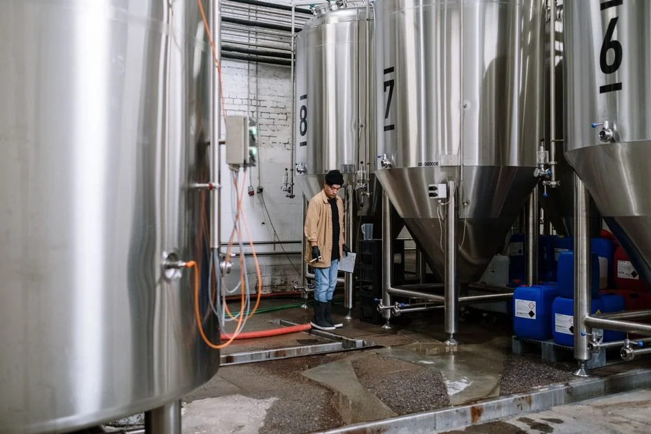
A defensible train for an expanded beverage plant runs in seven stages, each justified by what it specifically removes from this wastewater. Stage 1 is coarse screening with a rotary bar screen sized to protect downstream pumps and any MBR cassettes from label, cap and broken-glass carry-over. Stage 2 is flow and load equalisation with auto pH correction: design retention of 8–12 hours at peak flow, with submerged mixers and online pH/conductivity probes so the biology downstream sees a stable substrate (per WTE equalisation guidance, 2025). Stage 3 is dissolved air flotation — a DAF system in the 4–300 m³/h range with a polyaluminium chloride or ferric coagulant and a polyacrylamide flocculant dosed via an automatic chemical dosing system; on food effluent, DAF reliably removes 60–90% of FOG and 30–50% of colloidal COD, which protects the downstream biology from oil coating and floatation loss. Stage 4 is the biological step — MBBR, SBR or MBR, selected as described in the next section. Stage 5 is solid–liquid separation: a secondary clarifier for MBBR/SBR, or for MBR the membrane cassette itself replaces the clarifier entirely. Stage 6 is tertiary polishing for discharge or reuse: a multi-media filter ahead of a reverse osmosis (RO) system for reuse-grade water, with on-site generated chlorine dioxide from a chlorine dioxide generator for disinfection (50 g/h to 20,000 g/h range) — ClO₂ is preferred over chlorine because it does not form trihalomethanes that would taint any reused water sent to CIP. Stage 7 is sludge handling: a lamella thickener on the DAF float plus a plate-and-frame filter press for the combined biological and float sludge to reach 18–22% DS for off-site disposal. The biological step itself is delivered as an MBR membrane bioreactor system when reuse or brownfield footprint is the binding constraint.
MBBR vs SBR vs MBR: Choosing the Right Biology for an Expansion
The single most consequential technology decision in a beverage ETP expansion is the choice of biological reactor, because it locks in 60–70% of both the footprint and the lifecycle OPEX for the next 15 years. MBBR is a moving-bed biofilm system that handles load swings well, has no membrane replacement cost, and produces an effluent typically around BOD 20–30 mg/L and TSS 20–40 mg/L — sufficient for sewer discharge but marginal for direct reuse (per WTE MBBR description, 2025). SBR is a batch-fill, react, settle, decant sequence; it is mechanically simple and tolerant of variable strength, but its footprint is roughly 1.8–2.2× that of an MBR at the same load, and it requires careful cycle management to handle a beverage plant's diurnal pattern. MBR delivers the best effluent quality — typically BOD <5 mg/L, COD <50 mg/L, TSS near zero — and replaces the secondary clarifier entirely, so the total plot is roughly 60% smaller than the equivalent MBBR or SBR train at the same load, which is decisive on a constrained brownfield (per HydropureWater MBR product spec, 2025). The decision rule of thumb: choose MBBR when the only objective is discharge compliance at the lowest lifecycle cost; choose MBR when reuse water is targeted, or when the available civil footprint is the binding constraint; choose SBR only at very low flows where intermittent operation matches production.
| Criterion | MBBR | SBR | MBR |
|---|---|---|---|
| Footprint at same BOD load | 1.0× (reference) | 1.8–2.2× | 0.35–0.45× |
| Effluent BOD, mg/L | 20–30 | 15–25 | <5 |
| Effluent TSS, mg/L | 20–40 | 15–30 | <1 (turbidity <1 NTU) |
| Load-shock tolerance | High (biofilm) | Moderate (buffered by cycle) | Moderate–high (with equalisation) |
| Reuse suitability | Marginal | Marginal | Direct feed to RO |
| Membrane / media replacement | Carrier media 15+ yr | None | Membranes 5–8 yr |
| CAPEX direction (vs MBBR) | Baseline | −5% to −10% | +30% to +50% |
| OPEX direction (vs MBBR) | Baseline | −5% (less aeration) | +15% to +25% (membrane aeration, CIP) |
| Best fit for beverage expansion | Discharge-only, greenfield, low capex priority | Very low / intermittent flow | Brownfield with reuse target |
For a deeper read on the operating-cost side of SBR versus other batch biology, the SBR energy efficiency guide gives a current aeration-kWh breakdown, and the granular activated sludge technology piece covers the newer high-rate aerobic granule option that sits between MBBR and MBR in footprint.
Sizing a Beverage ETP for a 500 m³/day Expansion
Take a working example: an existing plant at 500 m³/day commissions a new bottling line that adds roughly 300 m³/day on the average day, but the combined site will see peak hourly flows of about 400 m³/day-equivalent when the existing line is in CIP and the new line is mid-syrup. The new biological stage should therefore be designed for 400 m³/day at 1,200 mg/L BOD, which is 480 kg BOD/day. With MBBR, the working MLVSS-equivalent loading rate of about 0.6–0.8 kg BOD/m³·d implies a reactor volume in the 600–800 m³ range; with MBR, the same load is handled in roughly 250–350 m³ of tankage plus the membrane cassette, which is why MBR is the typical answer for a constrained brownfield (per HydropureWater MBR product spec, 2025). Equalisation should hold 8–12 hours of peak flow — roughly 200 m³ for this example — so a CIP dump does not hit the biology as a slug (per WTE equalisation guidance, 2025). DAF is selected on hydraulic loading for food-industry FOG in the 20–30 m³/m²·h band; the DAF product range covers 4–300 m³/h, so a single unit covers this expansion flow with margin. Membrane flux for an MBR on high-strength food effluent typically runs in the 15–25 LMH range at 10–35 °C, which sets the membrane area and air-scour demand — a useful design check, though the precise figure should be confirmed by jar testing and pilot operation on the actual effluent rather than borrowed from a textbook. Sludge yield is in the band of 0.3–0.5 kg DS per kg BOD removed for the biological stage plus float from DAF, so a plate and frame filter press in the 1–500 m² plate-area range handles dewatering for any expansion up to roughly 1,500 m³/day. Pre-sedimentation of the raw influent is rarely needed once DAF is in place; where pre-clarification is desired, a high-efficiency sedimentation tank is used as a guard stage ahead of DAF.
Discharge Compliance and Water Reuse for an Expanded Beverage ETP
Typical municipal sewer discharge norms for an Indian or comparable Asian soft-drink plant sit around BOD <30 mg/L, COD <125 mg/L, TSS <50 mg/L, pH 6.5–8.5 and FOG <10 mg/L — these are illustrative ranges, not regulatory text, and the actual limits depend on the consent letter and the receiving body (per WTE typical reduction list, 2025). If the treated stream is to be reused for CIP dilution, boiler feed or cooling-tower make-up, a multi-media filter plus RO is required; modern RO units on beverage reuse routinely achieve 70–95% recovery depending on feed salinity and temperature (per HydropureWater RO spec, 2025). Disinfection is best handled with on-site generated chlorine dioxide rather than sodium hypochlorite, because ClO₂ does not produce the trihalomethanes that can carry through to product-contact surfaces in a soft-drink plant (per HydropureWater ClO₂ generator spec, 2025). For early warning of biology upset, install online ammonia and pH analysers on the aeration tank — the typical CAPEX band for an online ammonia analyser is roughly USD 8,000–45,000 per analyser depending on spec, which is covered in more detail in the online ammonia analyzer buyer's guide, and the broader reuse and ZLD outlook is set out in the 2026 water reuse outlook.
Frequently Asked Questions
What influent BOD and COD should a beverage ETP be designed for after a capacity expansion?
For a soft-drink or syrup plant post-expansion, design the ETP at BOD 800–1,500 mg/L, COD 1,500–3,000 mg/L, TSS 600–1,200 mg/L and pH 4–11, with the upper ends reserved for plants that include a sugar-inversion room and bottle-washer CIP. Use 1.2–1.4× the peak day flow as the hydraulic design basis so the train can absorb a simultaneous CIP dump (per WTE industrial guide, 2025; WCSP beverage case study, 2025).
Should we expand the existing ETP in place or build a parallel train for a new bottling line?
If the existing biology is below about 70% of its MLVSS-equivalent capacity and the plot can accept the new equalisation tank, expanding in place is normally 20–35% cheaper on capex. If the existing reactor is already above 70% load, or if any product launch is planned within three years, install a parallel dedicated beverage train — typically built around an MBR membrane bioreactor system with a DAF front-end — so the new line can be commissioned independently of the legacy unit.
MBBR, SBR or MBR — which is the right biology for a high-strength sugar-bearing beverage effluent?
Pick MBBR when the only objective is discharge compliance and capex is the binding constraint — effluent settles around BOD 20–30 mg/L. Pick SBR only at low and intermittent flows, because its footprint is roughly 2× MBR. Pick MBR when reuse water is targeted or the brownfield footprint is the binding constraint, since it delivers BOD <5 mg/L and replaces the secondary clarifier (per WTE biology descriptions, 2025; HydropureWater MBR product spec, 2025).
Is a DAF unit really necessary ahead of the biological stage on a beverage plant?
Yes. A DAF system ahead of biology removes 60–90% of FOG and a significant fraction of colloidal COD from syrup and bottle-wash carry-over, which prevents oil coating of the biomass and reduces the load on the downstream reactor by 25–40%. Skipping DAF is the most common reason beverage MBBRs and SBRs lose mixed-liquor settleability within the first six months of operation.
What reuse rate can a beverage plant realistically target after expanding the ETP?
With MBR effluent fed through a multi-media filter and RO, beverage plants routinely achieve 50–70% reuse of the treated stream for cooling-tower make-up, garden and CIP dilution, and up to 80–90% when the cooling-tower loop accepts higher TDS. RO recovery on a well-pretreated feed is typically 70–95% (per HydropureWater RO spec, 2025). The reused stream should be disinfected with on-site generated chlorine dioxide rather than chlorine to avoid trihalomethane formation in the product-contact zone.