How Secondary Clarifiers Work: The Physics of Sedimentation and Flocculation
Secondary clarifiers utilize gravity-driven phase separation where the terminal settling velocity of biological flocs must exceed the upward hydraulic velocity of the liquid stream to prevent solids carryover. This process is governed fundamentally by Stokes’ Law, which defines the settling velocity (v) as v = (g(ρₚ-ρₗ)d²)/(18μ), where g is gravitational acceleration, ρₚ and ρₗ are the densities of the particle and liquid, d is the particle diameter, and μ is the dynamic viscosity of the fluid. However, in an activated sludge environment, Stokes’ Law is limited by the fact that biological flocs are non-spherical, porous, and subject to hindered settling as concentrations increase.
Effective sedimentation begins with floc formation, a bio-chemical process where microorganisms produce extracellular polymeric substances (EPS). These polymers act as biological glue, binding individual bacteria into stable, settleable aggregates. For optimal performance, engineers target a floc size between 100 and 500 μm. If flocs are too small (pin floc), they remain suspended; if they are too light or filamentous, they resist downward movement, leading to high effluent Total Suspended Solids (TSS).
Within a secondary clarifier, four distinct settling zones occur based on depth and solids concentration:
- Discrete Settling: Occurs in the uppermost clarified zone where particles settle independently without interaction.
- Flocculent Settling: Particles collide and aggregate as they fall, increasing in mass and settling velocity.
- Hindered (Zone) Settling: Typically occurring at depths of 0.5–1.5 m, where high solids concentrations (MLSS) cause particles to settle as a unified mass or "blanket."
- Compression Settling: In the bottom-most layer, the weight of the overlying solids physically squeezes water out of the sludge matrix, thickening the underflow.
Operational efficiency is highly sensitive to Mixed Liquor Suspended Solids (MLSS) concentrations. While conventional activated sludge systems operate at 1,500–4,000 mg/L, modern Membrane Bioreactor (MBR) systems or high-rate processes may reach 6,000–12,000 mg/L (per WEF 2023 guidelines), necessitating significantly larger clarifier surface areas or advanced lamella clarifier for compact footprint and 30% lower chemical use to maintain separation efficiency.
Critical Design Parameters: SOR, SLR, and RAS Rates for 95%+ TSS Removal
Hydraulic and solids loading rates directly dictate the required surface area and depth of a secondary clarifier to maintain effluent total suspended solids (TSS) below 20 mg/L. The Surface Overflow Rate (SOR) represents the volume of water applied per unit of surface area per day. Per EPA 2024 benchmarks, municipal systems generally target 16–24 m³/m²/day, while industrial applications—often dealing with more robust, dense flocs—can operate at 24–32 m³/m²/day. Exceeding these limits creates upward velocities that overcome the settling speed of the biomass, resulting in "washout."
The Solids Loading Rate (SLR) is arguably the more critical parameter for secondary clarification, as it accounts for both the influent flow and the Return Activated Sludge (RAS) flow. Citing WEF 2023 data, an SLR exceeding 6 kg/m²/day typically correlates with a 40% increase in effluent TSS. For industrial plants with high-strength waste, such as pulp and paper, SLRs may be pushed to 8 kg/m²/day, provided the Sludge Volume Index (SVI) remains stable.
| Parameter | Municipal Standard (EPA 2024) | Industrial Standard (Zhongsheng Data) | Impact of Exceeding Limit |
|---|---|---|---|
| Surface Overflow Rate (SOR) | 16–24 m³/m²/day | 24–32 m³/m²/day | Hydraulic washout; TSS >30 mg/L |
| Solids Loading Rate (SLR) | 3–5 kg/m²/day | 5–8 kg/m²/day | Blanket rise; oxygen depletion in sludge |
| RAS Flow Rate | 25–50% of influent | 50–100% (High-rate) | Inadequate MLSS in aeration tank |
| Sludge Blanket Depth | 0.3–1.0 m | 0.5–1.2 m | Denitrification and rising sludge |
Managing the Return Activated Sludge (RAS) rate is the primary lever for operator control. In systems requiring full nitrification, RAS rates often exceed 100% to ensure rapid removal of biomass from the clarifier before denitrification occurs. For example, a plant with a 10,000 m³/day influent flow operating at a 30% RAS rate must pump 3,000 m³/day of settled sludge back to the head of the biological process. Operators must also monitor the sludge blanket depth using a "sludge judge" or ultrasonic sensor; a depth exceeding 1.5 m significantly increases the risk of TSS spikes due to turbulence and reduced settling volume.
This understanding of clarifier operations is critical to optimizing performance and preventing common issues. With this in mind, the design and operation of secondary clarifiers can be tailored to meet specific wastewater treatment needs.
Circular vs. Rectangular Clarifiers: Performance, Cost, and Use-Case Matching
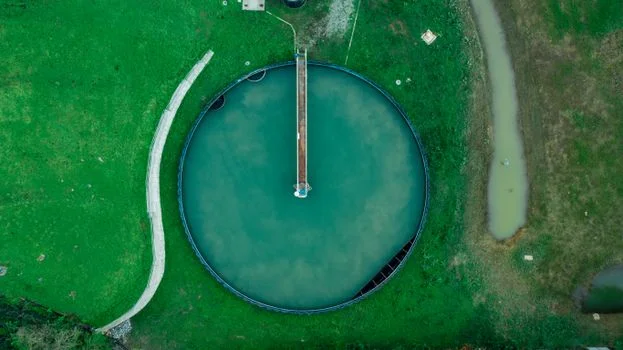
Circular clarifiers account for approximately 78% of municipal wastewater installations globally due to their efficient sludge collection mechanisms and lower structural costs per cubic meter of treated volume (per WEF 2023). These units typically utilize a center-feed, peripheral-overflow design, which maximizes the flow path and encourages flocculation. In contrast, rectangular clarifiers are favored in 65% of industrial installations, particularly in the pulp, paper, and food processing sectors, where space constraints and the need for modular expansion are paramount.
Rectangular units operate with a length-to-width ratio of 3:1 to 5:1, utilizing chain-and-flight scraper mechanisms to move sludge to a collection hopper. While they offer a smaller footprint (0.03 m²/m³ compared to 0.05 m²/m³ for circular), they carry higher maintenance costs due to the mechanical complexity of the underwater chains. Circular clarifiers, with CapEx ranging from $120–$250/m³, offer superior TSS removal (92–97%) for low-solids municipal waste. Rectangular units, despite a higher CapEx of $180–$350/m³, excel at handling high-solids industrial loads where footprint is at a premium.
| Feature | Circular Clarifier | Rectangular Clarifier | Lamella Clarifier (Alternative) |
|---|---|---|---|
| TSS Removal Efficiency | 92–97% | 90–95% | 95–99% |
| Footprint Requirement | High (0.05 m²/m³) | Medium (0.03 m²/m³) | Very Low (0.01 m²/m³) |
| Energy Consumption | 0.02 kWh/m³ | 0.03 kWh/m³ | 0.01 kWh/m³ |
| Primary Application | Municipal / Large Flow | Industrial / Restricted Space | High-Solids / Retrofits |
Selection depends heavily on the specific wastewater characteristics. Circular designs are ideal for consistent, low-SVI municipal sludge. However, for dairy or textile applications where solids loading can fluctuate wildly, the hydraulic stability of a rectangular basin or the high-efficiency settling plates of a lamella clarifier design specs and performance benchmarks provide better process security. For plants struggling with sludge volume, integrated sludge dewatering systems to handle clarifier underflow are often required to manage the thickened solids effectively.
Troubleshooting Secondary Clarifier Failures: A Step-by-Step Diagnostic Guide
Operational failures in secondary clarifiers typically manifest as "sludge bulking" or "rising sludge," phenomena driven by microbial morphology or uncontrolled denitrification within the sludge blanket. When effluent TSS exceeds 30 mg/L, operators must immediately measure the Sludge Volume Index (SVI). An SVI >150 mL/g indicates filamentous bulking, often caused by low dissolved oxygen (DO) or nutrient deficiencies in the aeration tank. This can be mitigated by implementing an automated polymer dosing to prevent bulking sludge, which increases floc density and settling speed.
Rising sludge is a distinct issue caused by denitrification, where nitrate (NO₃) is converted to nitrogen gas (N₂) in the anaerobic environment of a deep sludge blanket. The gas bubbles attach to flocs, causing them to float to the surface. This is diagnosed by observing "clumps" of sludge on the surface and is fixed by increasing the RAS rate to reduce the residence time of the sludge in the clarifier. Short-circuiting, another common failure, occurs when influent baffles fail, allowing wastewater to bypass the settling zones and exit directly through the weirs.
Diagnostic Flowchart for High Effluent TSS:
- Measure Effluent TSS: Is TSS >30 mg/L? If yes, proceed.
- Measure SVI: Is SVI >150 mL/g?
- Yes: Filamentous bulking. Check DO levels in aeration; apply coagulants/polymers.
- No: Proceed to step 3.
- Inspect Sludge Blanket: Is blanket depth >1.5 m?
- Yes: SLR is overloaded or RAS rate is too low. Increase RAS flow to 50–70%.
- No: Proceed to step 4.
- Check for Gas Bubbles: Is sludge "clumping" on the surface?
- Yes: Denitrification. Increase RAS rate or reduce MLSS via wasting (WAS).
- No: Inspect for mechanical short-circuiting or weir misalignment.
CapEx and OPEX Breakdown: Secondary Clarifier Costs for Municipal and Industrial Plants
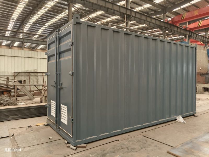
Capital expenditure (CapEx) for secondary clarifiers ranges from $120 to $350 per m³ of treated capacity, with material selection and site-specific geotechnical requirements serving as the primary cost drivers. Concrete basins are standard for municipal plants with diameters exceeding 30 m, whereas stainless steel or epoxy-coated carbon steel tanks are preferred for industrial modular systems. According to 2025 RSMeans data, the mechanical components—including scrapers, drives, and weirs—account for approximately 40% of the total CapEx.
Operating expenses (OPEX) are dominated by energy consumption and labor. While the scraper drive itself consumes minimal power (0.02–0.03 kWh/m³), the associated RAS pumping can account for 15–20% of a plant's total energy bill. Chemical costs, primarily for polymers used during