Why metals-laden mining process water is uniquely hard on RO membranes
Colloidal solids — not dissolved metals — cause 60–80% of premature reverse osmosis (RO) membrane failure in base-metal hydrometallurgy circuits, based on HydropureWater field data from 2024–2025 mining retrofits. Metals-laden process water at a copper, zinc, gold, or nickel operation covers a wide envelope: bleed streams from flotation, thickening overflow, acid mine drainage (AMD) neutralization effluent, heap-leach bleed, and solvent extraction (SX) settler overflow. Typical feed runs 50–5,000 ppm total suspended solids (TSS), turbidity of 100–3,000 NTU, iron 5–500 mg/L, manganese 0.5–50 mg/L, with sub-10 μm colloidal clays, silica, and metal hydroxides always present (HydropureWater field data, 2025).
These colloids compact into a low-permeability cake on the RO membrane surface, raise differential pressure (ΔP) element-by-element, and cannot be removed by reverse-direction flushing the way mineral scale can. The standard RO feed targets make the bar explicit: SDI₁₅ < 5 for conventional brackish-water RO and SDI₁₅ < 3 for high-recovery or brine-concentrating systems (per HydropureWater UF field data; consistent with ASTM D4189-22). Operating above SDI₁₅ = 5 shortens membrane life from a nominal 5+ years to under 18 months in mining service — and the replacement cost at a remote site typically exceeds the entire pretreatment skid capital cost.
The two technologies competing for the slot directly in front of the RO are ultrafiltration (UF) and dissolved air flotation (DAF). They solve different parts of the problem, and the rest of this article shows how to pick the right one for metals-laden feed.
How DAF works in a mining context
A DAF unit separates suspended solids by attaching 10–100 μm micro-bubbles to conditioned particles and floating them to the surface, where a skimmer removes the sludge layer. The micro-bubbles are generated by pressurizing a clarified recycle stream to 60–120 psig with air, holding it in a saturation tank to dissolve the gas, then releasing it at the bottom of the flotation cell; the sudden pressure drop nucleates a cloud of bubbles that contacts the flocculated feed (per ScienceDirect DAF overview, 2025).
Two design numbers govern DAF capacity. The air-to-solids (A/S) ratio must sit in the 0.02–0.06 range — too low and particles don't float, too high and coalesced bubbles cause turbulence that tears the sludge blanket apart (per ScienceDirect DAF overview, 2025). The air concentration the saturator can hold follows Henry's law: ~24 ppm air at 1 atm rises to ~130 ppm theoretical at ~90 psig, then a 0.5–0.8 dissolution efficiency factor is applied to get the real number. That efficiency factor is why plants run a 10–30% recycle stream at pressure rather than pressurizing the full forward flow — direct pressurization shears flocs and is rarely used in industrial mining service.
DAF does not work on raw mining feed. Sub-50 μm colloids — which is most of what damages RO — do not attach to bubbles without coagulation and flocculation chemistry, so DAF must be preceded by a coagulant dose (ferric chloride, alum, or polyaluminum chloride) and a flocculant/polymer dose tuned to the feed. When dosed correctly, DAF excels at: removing free oil from SX crud breakthrough, floating metal-hydroxide flocs after lime neutralization, capturing coarse suspended solids at very high flow rates (often the cheapest m² of footprint in a mining plant), and acting as a thickener for tailings dewatering water. A HydropureWater DAF system is sized on these parameters and ships with the saturation tank, recycle pump, and skimmer drive integrated.
| DAF design parameter | Typical mining value | Source / note |
|---|---|---|
| Saturation pressure | 60–120 psig | ScienceDirect DAF overview, 2025 |
| Air-to-solids (A/S) ratio | 0.02–0.06 | ScienceDirect DAF overview, 2025 |
| Air solubility at ~90 psig (theoretical) | ~130 ppm | Henry's law (per ScienceDirect) |
| Dissolution efficiency factor | 0.5–0.8 | ScienceDirect DAF overview, 2025 |
| Recycle ratio | 10–30% of forward flow | HydropureWater field data, 2025 |
| Flotation tank retention time | 15–30 min | HydropureWater DAF design spec |
| Required upstream chemistry | Coagulant + flocculant/polymer | ScienceDirect DAF overview, 2025 |
How UF works in a mining context
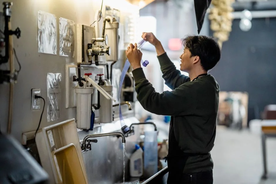
A 0.03 μm PVDF hollow-fiber UF is an absolute size-exclusion barrier: any particle above the pore rating is held outside the fiber lumen or on its surface, regardless of feed chemistry or whether a bubble attaches. The fibers are run in dead-end mode with periodic backwash and air scour, so the operating flux stays high and the feed-side pressure drop stays low. A HydropureWater hollow-fiber UF system tolerates up to 300 ppm turbidity in the feed, with automatic backwash, air-scour, and chemically enhanced backwash (CEB) handling the variable spikes that are normal in mining thickener overflow and AMD neutralized effluent.
Colloidal removal is deterministic. The system removes > 99% of particles above 0.03 μm, delivers consistent SDI₁₅ < 3 output (per HydropureWater UF field data, 2025), and provides ~4-log reduction in iron-bearing colloids and clay fines. Mining-specific foulants — ferric hydroxide, manganese dioxide, colloidal silica, and clay fines — are handled because they are larger than the pore, not because the chemistry is right. No air-to-solids ratio to maintain, no flocculant tuning to chase, no bubble attachment to hope for.
UF does have an upstream burden, and that is what DAF is for in a hybrid train. UF membranes will foul prematurely if the feed carries free oil, FOG, or very high TSS (e.g., > 300 NTU turbidity without pre-clarification). The standard pattern is a multi-media filter or DAF upstream of UF to drop the bulk solids, then UF as the colloidal barrier in front of RO.
| UF design parameter | Typical mining value | Source / note |
|---|---|---|
| Membrane nominal pore size | 0.03 μm (PVDF hollow fiber) | HydropureWater UF spec, 2025 |
| Operating flux | 50–80 LMH | HydropureWater UF field data, 2025 |
| Max feed turbidity | 300 NTU continuous | HydropureWater UF spec |
| Backwash water consumption | 5–10% of throughput | HydropureWater UF field data, 2025 |
| Effluent turbidity | < 0.2 NTU | HydropureWater UF field data, 2025 |
| Effluent SDI₁₅ | < 3 consistently | HydropureWater UF field data, 2025 |
| Iron-bearing colloid removal | ~4-log reduction | HydropureWater UF field data, 2025 |
Head-to-head: colloidal solids, SDI, footprint, chemistry
Side-by-side, the two technologies answer different questions. DAF is a clarifier; UF is a colloidal barrier. On the axes that matter for RO survival — effluent SDI₁₅ and turbidity — UF clears the RO bar directly and DAF does not. DAF effluent turbidity typically lands in the 5–20 NTU band with SDI₁₅ of 4–7 (HydropureWater field data, 2025; consistent with ScienceDirect DAF overview, 2025), which fails the SDI₁₅ < 3 target for high-recovery RO. UF effluent at < 0.2 NTU and SDI₁₅ < 3 sits comfortably below the threshold and is consistent across feed spikes that would push DAF outside its operating envelope.
On footprint, DAF tanks require 15–30 min hydraulic retention and therefore a large civil footprint — typically 25–40 m² per 100 m³/h of forward flow. UF skids run at 50–80 LMH flux in compact modules and fit inside a standard containerized building at the same flow.
On chemistry, DAF needs continuous coagulant + flocculant/polymer dosing with day-to-day jar-test tuning; UF needs only periodic clean-in-place (CIP) every 1–4 weeks with dilute acid or sodium hypochlorite. For a remote mining site with limited chemical logistics and a small operator pool, that chemistry difference is decisive.
| Axis | DAF | UF (0.03 μm PVDF) |
|---|---|---|
| Colloidal removal mechanism | Bubble attachment to floc | Absolute size exclusion (0.03 μm) |
| SDI₁₅ effluent | 4–7 (fails RO target) | < 3 (clears RO target) |
| Effluent turbidity | 5–20 NTU | < 0.2 NTU |
| Typical effluent TSS | 10–30 mg/L | < 1 mg/L |
| Footprint per 100 m³/h | 25–40 m² (tank) | ~6–10 m² (skid) |
| Chemical demand | Coagulant + flocculant + polymer continuous | CIP acid + hypochlorite, weekly–monthly |
| Sensitivity to feed spikes | High (chemistry-dependent) | Low (barrier-dependent) |
| Operator skill required | Skilled (jar testing, polymer tuning) | Standard (membrane skid) |
CAPEX and OPEX reality for a 100 m³/h mining RO pretreatment train
At 100 m³/h, a DAF-only train is the lowest install cost — no membrane building, no membrane replacement line item, lower electrical. A DAF + UF train carries the incremental cost of the UF skid, the backwash pumps, the CIP skid, and the building to house it. That incremental spend is recovered through longer RO membrane life, lower RO CIP frequency, and lower chemistry spend on the RO side (HydropureWater field data, 2025).
OPEX drivers split cleanly. DAF consumes coagulant (typically ferric chloride at 50–150 mg/L), flocculant/polymer (1–5 mg/L), compressed air, and skimmer maintenance. UF consumes backwash water at 5–10% of throughput, plus periodic CIP chemicals. The biggest line item in the OPEX stack, however, is on the RO side: RO CIP frequency drops 50–80% when the RO is protected by UF versus DAF alone, and RO membrane life extends from ~18 months back toward 5+ years (HydropureWater field data, 2025).
The hidden cost that drives the financial decision is one premature RO membrane replacement set at a remote site. Freight, lost production, and the membrane elements themselves routinely exceed the entire UF skid CAPEX for a 100 m³/h train. UF is therefore the lower-risk financial choice even when its first cost is higher. Operators lock in lifecycle cost by standardizing on the HydropureWater DAF system as the primary clarifier, the HydropureWater hollow-fiber UF system as the colloidal barrier, and a stocked replacement UF and RO membrane elements program on site to cut freight and downtime.
| Cost line (100 m³/h train) | DAF only | DAF + UF | Source / note |
|---|---|---|---|
| Installed pretreatment CAPEX | Lower (baseline) | + ~40–70% over DAF only | HydropureWater field data, 2025 |
| Coagulant + flocculant OPEX | High (continuous) | High (DAF section) + low (UF section) | HydropureWater field data, 2025 |
| UF backwash + CIP OPEX | None | 5–10% of throughput + monthly CIP | HydropureWater UF spec |
| RO CIP frequency | Baseline (high) | ↓ 50–80% vs DAF only | HydropureWater field data, 2025 |
| RO membrane replacement interval | ~18 months | ~5+ years | HydropureWater field data, 2025 |
| Single-event RO replacement cost (remote site) | Reference | Often > UF skid CAPEX | HydropureWater field data, 2025 |
When DAF still wins, and the recommended mining train
DAF is the right answer when the goal is oil/FOG removal, very high flow with simple bulk-solids reduction, or thickening for tailings dewatering rather than RO polishing. If the feed carries SX crud breakthrough, free oil, or TSS so high that UF would foul too fast without pre-clarification, DAF earns its slot upstream of UF. For feeds with low oil, low TSS, and turbidity under ~200 NTU, the DAF can be skipped: a multi-media filter ahead of UF is enough, saving CAPEX and floor space.
The recommended default mining train for a copper, zinc, gold, or nickel operation feeding an industrial RO system the pretreatment train is protecting is: equalization basin → pH adjustment (lime or caustic) → ferric coagulation via an automatic chemical dosing for coagulation and pH adjustment → DAF (oil/FOG/floc removal) → multimedia polisher → UF → RO, with RO reject optionally sent to a brine management or crystallizer stage. For a deeper read on DAF sizing versus conventional clarifiers at a specific site, see the DAF vs clarifier guide for mining wastewater. For cross-industry comparison, the UF vs DAF guide for food and beverage process water and the UF vs DAF guide for pharmaceutical API wastewater show the same framework applied to different feeds.
For colloidal solids specifically, UF wins the slot directly in front of the RO. DAF wins the upstream clarifier slot, not the slot the RO sees. That is the decision rule to take into a CAPEX meeting.
Frequently Asked Questions
Does UF always need a DAF or clarifier upstream in a mining RO train?
Not always. If feed turbidity stays under ~200 NTU, oil/FOG is absent, and TSS is under ~50 ppm, a multi-media filter can replace DAF upstream of UF; the train is then equalization → MMF → UF → RO. Above those thresholds, or whenever free oil from SX crud breakthrough is possible, DAF earns its slot (HydropureWater field data, 2025).
What A/S ratio and saturation pressure should a mining DAF be designed for?
Target A/S of 0.02–0.06 and saturation pressure of 60–120 psig, with a recycle ratio of 10–30% and a dissolution efficiency factor of 0.5–0.8 applied to the theoretical Henry's-law air concentration (per ScienceDirect DAF overview, 2025). The DAF ships with these as default operating ranges.
What SDI₁₅ does UF guarantee in front of an RO at a copper or gold plant?
Consistently SDI₁₅ < 3 across feed turbidity up to 300 NTU, with effluent turbidity under 0.2 NTU and ~4-log reduction in iron-bearing colloids and clay fines (HydropureWater UF field data, 2025). That is below the SDI₁₅ < 5 conventional RO target and clears the SDI₁₅ < 3 high-recovery RO target.
How much does RO membrane life extend when UF replaces DAF as the direct pretreatment?
From roughly 18 months to 5+ years in mining service, with RO CIP frequency dropping 50–80% over the same period (HydropureWater field data, 2025). The single-event cost of one premature RO replacement at a remote site typically exceeds the entire UF skid CAPEX for a 100 m³/h train, which is why the incremental UF CAPEX is recovered through avoided RO replacement.