Why Battery Recycling Wastewater Is a Different Problem
Battery recycling wastewater is a four-stream composite — hydrometallurgical leachate, NMP recovery condensate, black mass wash water, and MVR distillate — that breaks the assumptions built into municipal and generic industrial wastewater design. Combined pollutant loadings sit in the range of COD 1,500–8,000 mg/L, fluoride 500–3,000 mg/L, NH3-N 200–1,200 mg/L, and total heavy metals (Co+Ni+Mn+Li) often 200–1,500 mg/L, which is well above what a standard activated-sludge plant can absorb. The BOD/COD ratio is typically below 0.20 because NMP solvent and LiPF6 hydrolysis products are refractory; this rules out biological treatment as the first stage and forces a chemistry-led train. Global lithium-ion battery recycling capacity is projected to exceed 1.2 million tonnes per year by 2026 (per industry forecasts, 2025-12), which moves this from a one-off design problem to a recurring engineering one for any gigafactory or hydrometallurgical recycler planning a new line. The takeaway: lithium battery recycling wastewater treatment process design must start from the chemistry of cathode leaching and electrolyte breakdown, not from a copy-paste of municipal design rules.
Influent Characterization by Process Source
You cannot select unit operations until each stream is characterized, because the four streams behave differently and sometimes need to be segregated at the head of the plant. The table below captures the typical envelope a designer should expect in 2026 (per HydropureWater field data, 2025-11; typical ranges across Chinese hydrometallurgical recyclers).
| Stream | pH | COD (mg/L) | BOD/COD | Fluoride (mg/L) | NH3-N (mg/L) | TSS (mg/L) | Total heavy metals (mg/L) | Conductivity (µS/cm) |
|---|---|---|---|---|---|---|---|---|
| Hydrometallurgical leachate | 1–3 | 2,000–8,000 | <0.20 | 500–3,000 | 200–1,200 | 200–800 | 500–1,500 | 15,000–40,000 |
| NMP recovery condensate | 6–9 | 5,000–25,000 | <0.15 | <50 | 50–200 | 100–400 | <50 | 2,000–8,000 |
| Black mass wash water | 6–8 | 1,500–4,000 | 0.20–0.30 | 100–500 | 50–300 | 5,000–20,000 (2–8% solids) | 200–800 | 5,000–15,000 |
| MVR distillate | 4–7 | 1,000–3,000 | 0.10–0.20 | 200–1,000 | 300–1,000 | <50 | 50–200 | 3,000–10,000 |
Two facts from this matrix drive the rest of the design. First, LiPF6 hydrolysis — LiPF6 + 4 H2O → LiF + 5 HF + H3PO3 — is the dominant fluoride source, with peak F− loadings during cathode leaching when temperature and acid activity are highest. Second, NMP recovery condensate carries COD 5,000–25,000 mg/L at BOD/COD below 0.15, which means it will not respond to raw biological treatment and must be routed through Fenton or ozone polishing first. Black mass wash water is the dirty stream by volume of solids, typically 2–8%, so it should pass screening and a DAF unit before any chemistry stage to protect downstream pumps and membranes.
The 2026 Process Flow: From Pretreatment to Water Reuse
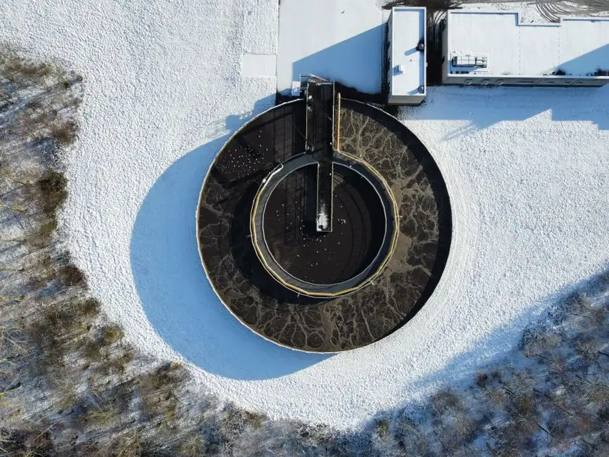
A defensible 2026 process train is built in six stages, sequenced to drop the most problematic parameters first and only feed clean water to the highest-cost polishing steps.
Stage 1 — Equalization and screening. A rotary mechanical bar screen for cathode fragment removal protects downstream equipment from plastic, separator, and current collector debris, followed by an equalization basin sized for 8–24 hours of hydraulic retention to dampen shock loads from batch leaching campaigns. Equalization is non-negotiable on a hydrometallurgical line where pH swings of 2–3 units between batches are common.
Stage 2 — pH adjustment and fluoride precipitation. Lime or CaCl2 dosing raises pH to 7–9, driving fluoride out as CaF2 sludge in a lamella clarifier for fluoride precipitation. Typical F− reduction is 500–3,000 mg/L down to under 15 mg/L, with sludge yield around 4–6 kg dry cake per m³ treated. Lamella geometry delivers 20–40 m/h surface loading versus 1–2 m/h for a conventional clarifier, which cuts tank footprint by roughly 60%.
Stage 3 — Heavy metal precipitation. NaOH or Na2S dosing at pH 9–10 drops Co, Ni, Mn, and Cu below 1 mg/L each. Na2S is the more reliable option when Cd and Cu dominate, because the sulfide Ksp values are 8–10 orders of magnitude lower than the hydroxide forms; metal recovery from the sulfide cake is also more selective if the line is set up for downstream hydromet recovery. Dosing is controlled by an automatic chemical dosing system for pH and fluoride control to keep reagent stoichiometry inside ±5%.
Stage 4 — Fenton oxidation for NMP and electrolyte COD. A Fenton reactor run at H2O2/Fe2+ molar ratio 3–8 and pH 3–4 delivers 40–70% COD reduction on NMP-laden streams. A working sizing rule is 1–2 g H2O2 per gram of COD removed; at that dose a 6,000 mg/L COD feed drops to roughly 1,800–3,600 mg/L, which is what an MBR can polish economically. For a deeper treatment walkthrough see this Fenton oxidation system design reference for refractory COD.
Stage 5 — MBR biological polishing. A submerged DF series PVDF flat sheet MBR module with 0.1 µm pore size takes Fenton effluent to COD under 50 mg/L and NH3-N under 5 mg/L after nitrification. The full MBR membrane bioreactor system for battery recycling wastewater cuts footprint by about 60% versus conventional activated sludge and produces a clarified feed that RO membranes can take directly. The MBR segment is one of the faster-growing lines in industrial wastewater — see MBR market growth 2026 for buyer-side data.
Stage 6 — RO for water reuse. An industrial RO system for battery recycling water reuse at 70–95% recovery produces a permeate suitable for black mass washing and NMP dilution, with concentrate returned to Stage 3 precipitation for residual metal recovery. The full operating logic of an RO train is covered in this RO system process and industrial design reference. For plants that want a single design covering both electrolyte streams and process rinse water, the integrated battery electrolyte wastewater recycling system provides a matched flowsheet.
Unit Operation Selection: When to Use DAF, Fenton, MBR, or RO
Engineers usually get stuck on which unit operation to slot in where. The matrix below maps each unit to a target pollutant, expected removal efficiency, footprint impact, dominant OPEX driver, and the trigger that should make you pick it.
| Unit operation | Target pollutant | Removal efficiency | Footprint impact | OPEX driver | When to choose |
|---|---|---|---|---|---|
| DAF system for black mass wash water pretreatment | TSS, emulsified oil | 85–95% | Compact (small footprint) | Polymer + electricity | Influent TSS >500 mg/L or visible oil/grease before Fenton |
| Lamella clarifier | Fluoride, metals (as CaF2, M(OH)x) | F− to <15 mg/L; metals <1 mg/L | 20–40 m/h surface loading; ~60% smaller than conventional | Lime/CaCl2 reagent | Always Stage 2/3 chemistry — high settling-rate sludge |
| Fenton oxidation | Refractory COD (NMP, electrolyte) | 40–70% COD reduction | Moderate; HRT 2–4 h | H2O2 + FeSO4 | COD <5,000 mg/L and chloride <5,000 mg/L |
| Ozone | Refractory COD, color | 30–60% COD reduction | Larger than Fenton | Power + O2 supply | Chloride <1,000 mg/L (avoids ClO2 formation) and color strip is required |
| MBR | Residual COD, NH3-N | COD <50 mg/L, NH3-N <5 mg/L | ~60% smaller than CAS | Membrane cleaning, aeration | Small footprint, direct RO feed, or flow <2,000 m³/day |
| SBR | Residual COD, NH3-N | COD <80 mg/L, NH3-N <10 mg/L | Larger than MBR | Lower energy, more operator attention | Flow >2,000 m³/day and stable influent (rare in recycling) |
| RO | Dissolved salts, residual metals | 70–95% recovery; >99% rejection of multivalent ions | Compact for the duty | Energy + membrane replacement | Only credible reuse step; concentrate loops to metal recovery |
Two practical rules from the field. Fenton is cheaper than ozone for COD under 5,000 mg/L, but ozone becomes the better pick when chloride drops below 1,000 mg/L because Fenton works poorly in low-chloride matrices and ozone avoids ClO2 formation risk. MBR is preferred over SBR whenever the plant is below about 2,000 m³/day or the influent is variable, which is the norm in batch-fed recycling operations.
2026 Compliance: Discharge Limits and Recovery Targets
The compliance picture for 2026 is shaped by three jurisdictions. China GB 30485-2020 (COD ≤500 mg/L, NH3-N ≤45 mg/L, fluoride ≤15 mg/L, total Ni/Co ≤1.0 mg/L for battery industry wastewater) replaces the 2013 version and tightens the fluoride ceiling from 20 mg/L to 15 mg/L. The EU Battery Regulation 2023/1542 sets minimum recycled-content targets of 16% Co, 6% Li, and 6% Ni by 2031, with the 2026 reporting cycle covering the first binding data set and pushing operators toward closed-loop water targets that an MBR+RO train directly supports. In the US, intact cells fall under RCRA universal waste rules, while dissolved metal discharge is controlled by state pretreatment programs — California BAT limits for Ni and Co are typically 1.0 mg/L and 1.0 mg/L respectively, aligning with the Chinese ceiling. The table summarizes the binding numbers a 2026 design must hit.
| Parameter | China GB 30485-2020 | EU 2023/1542 (effluent-related) | US (typical state BAT, e.g. CA) |
|---|---|---|---|
| COD | ≤500 mg/L | No direct limit; tied to local UWWTD/IED permits | State-specific, often 200–500 mg/L |
| NH3-N | ≤45 mg/L | Tied to local permit | 10–45 mg/L seasonal |
| Fluoride | ≤15 mg/L | Tied to local permit | 10–20 mg/L |
| Total Ni | ≤1.0 mg/L | Local permit; 50% recovery mandate by 2026 reporting | ≤1.0 mg/L (CA) |
| Total Co | ≤1.0 mg/L | Local permit; 80% Co recovery target by end of 2026 reporting cycle | ≤1.0 mg/L (CA) |
| Total Cu | ≤1.0 mg/L | Local permit; closed-loop water encouraged | ≤1.0 mg/L (CA) |
| pH | 6–9 | 6–9 (typical) | 6–9 |
A correctly designed MBR+RO train will meet GB 30485-2020 in a single pass and produces the closed-loop water data the EU reporting cycle requires.
Sludge and Reuse: Closing the Loop
No treatment train is complete until the residuals are closed. Fluoride precipitation generates 4–6 kg of dry CaF2 cake per cubic meter of treated wastewater, and the metal hydroxide/sulfide stage adds another 1–3% solids stream. A plate and frame filter press for fluoride and metal sludge in the 1–500 m² filter area range brings both cakes to ≥65% dryness, which is the threshold most off-site metal recovery smelters accept. RO concentrate is the third residual; the cheapest disposition is to route it back to the Stage 3 precipitation reactor, where residual Co and Ni report to the metal cake and effectively offset virgin reagent cost. The 70%+ wash water reuse rate from RO permeate is also a quantifiable 2026 ESG metric for gigafactory supply chains — it reduces raw water intake per kWh of battery produced, which several automaker disclosures now report on a plant-by-plant basis.
Frequently Asked Questions
What is the typical fluoride concentration in lithium battery recycling wastewater? Influent fluoride typically runs 500–3,000 mg/L, with the dominant source being LiPF6 hydrolysis during cathode leaching (LiPF6 + 4 H2O → LiF + 5 HF + H3PO3). A properly designed lime/CaCl2 precipitation stage followed by a lamella clarifier drops this to under 15 mg/L.
Can MBR alone treat NMP-bearing wastewater? No. NMP recovery condensate carries COD 5,000–25,000 mg/L at a BOD/COD ratio below 0.15, which makes it essentially non-biodegradable. Fenton or ozone oxidation must precede the MBR to break the NMP ring and lift the BOD/COD ratio above the 0.30 threshold where biomass can take over.
What 2026 discharge limits apply to cobalt and nickel in battery recycling effluent? China GB 30485-2020 sets both Co and Ni at ≤1.0 mg/L. EU 2023/1542 does not set a direct effluent limit, but mandates 80% Co recovery and 50% Ni recovery by the end of the 2026 reporting cycle, which effectively forces a sulfide precipitation + cake recovery design. US state pretreatment programs (e.g., California BAT) typically mirror the 1.0 mg/L ceiling.
How much water can a battery recycling plant reuse with RO? Industrial RO systems on this duty operate at 70–95% recovery, with concentrate returned to the upstream metal precipitation stage to recover residual Co and Ni. A 90% recovery target is realistic when influent TDS stays under 10,000 mg/L, which is achievable after the chemistry train.
What is the smallest viable system capacity for a battery recycling wastewater plant? Skid-mounted packaged plants are available from about 10 m³/day upward, with the practical commercial envelope running 10–200 m³/day for recycling demonstration lines. Below 10 m³/day the OPEX per m³ climbs sharply because chemistry dosing cannot be scaled linearly.