How an RO System Works Under Pressure
How an RO system works is straightforward: feed water is forced through a semipermeable membrane at 10–80 bar, rejecting 95–99% of dissolved salts, organics, and microorganisms into a concentrate while purified permeate passes. Industrial trains recover up to 95% of feed as permeate when SDI stays below 5 and free chlorine stays under 0.1 mg/L.
Osmosis, in its natural direction, moves water across a semipermeable membrane from the side with lower solute concentration to the side with higher solute concentration, equalizing chemical potential. The pressure that stops this flow is the osmotic pressure of the solution, roughly 0.7 bar for every 1,000 mg/L of TDS in a sodium chloride solution at 25°C. Reverse osmosis runs the process backwards: applied hydraulic pressure above the osmotic pressure reverses the net water flux, pushing water molecules through the membrane while hydrated ions, organics, and pathogens are size-excluded or charge-rejected.
Industrial RO uses crossflow filtration rather than dead-end filtration. Feed water sweeps tangentially across the membrane surface at 0.1–0.3 m/s, and the rejected contaminants leave as a concentrate stream. Without crossflow, fouling would accumulate within hours; with it, modern thin-film composite spiral wound elements can run 3–7 years between replacements. Rejection performance depends on the contaminant: 95–99% for monovalent ions like Na⁺ and Cl⁻, 99%+ for bacteria and viruses, and 90–99% for dissolved organics depending on molecular weight and membrane specification (HydropureWater field data, 2026). According to the U.S. Geological Survey, ocean water contains about 35,000 ppm of dissolved salt, which matches the seawater TDS basis used for SWRO pressure sizing.
Anatomy of a 4–6 Stage Industrial RO Skid
An industrial reverse osmosis skid is a six-stage process train where every component on the P&ID exists to either protect the membrane or condition the product water.
- Intake and pre-oxidation. Raw water enters from a well, surface source, or clarified effluent. Optional chlorine dioxide dosing controls biological growth through the pretreatment train; an integrated ClO₂ generator typically delivers 50–20,000 g/h depending on feed flow.
- Multi-media and activated carbon filtration. A multi-media pretreatment filter reduces turbidity from 10–50 NTU down to under 1 NTU and cuts the Silt Density Index (SDI₁₅) to below 5, the membrane protection threshold. Activated carbon strips free chlorine and reduces TOC.
- Cartridge filtration and antiscalant dosing. A 5-micron cartridge filter is the final guard before the high-pressure pump. An antiscalant and pH dosing system injects scale inhibitor (typically 1–5 mg/L) to prevent CaCO₃, CaSO₄, BaSO₄, and SiO₂ precipitation on the membrane surface.
- High-pressure pump and membrane vessels. A multistage centrifugal pump or positive-displacement pump boosts pressure to 10–15 bar for brackish water or 55–80 bar for seawater. FRP pressure vessels, each holding 4–8 spiral-wound 8-inch elements, are arranged in a 2:1 array so concentrate from the first pass feeds the second, lifting overall recovery.
- Permeate collection and post-treatment. Permeate flows to a storage tank, then through pH adjustment, UV sterilization at 30–40 mJ/cm², or remineralization depending on end use.
- CIP (clean-in-place) system. Acidic (pH 2) and alkaline (pH 11–12) cleaning loops allow membrane regeneration without disassembly, typically every 1–6 months depending on feed quality.
The full industrial RO system flow path runs feed → pretreatment → high-pressure pump → membrane array → permeate tank → post-treatment → distribution. Concentrate is discharged, sent to brine recovery, or routed to a downstream MBR process design before reuse. On compact campuses, permeate reuse often sits beside an Underground Package Sewage Treatment Plant (WSZ Series) that treats sanitary wastewater off the RO feed.
Key Performance Parameters: What the Numbers Mean
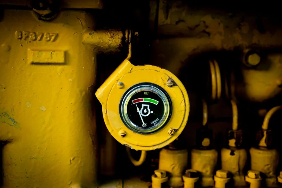
Five specific metrics define whether an RO system is performing as designed.
| Parameter | Brackish RO | Seawater RO | Notes |
|---|---|---|---|
| Rejection (NaCl) | 95–99.5% | 99–99.7% | Lower for silica, boron, low-MW organics |
| Recovery rate | 65–85% (up to 95%) | 40–50% | Higher recovery = higher scaling risk |
| Permeate flux | 10–20 LMH | 8–14 LMH | Excess flux causes compaction |
| Specific energy | 0.5–2 kWh/m³ | 3–6 kWh/m³ | ERDs cut SWRO by 30–60% |
| Membrane life | 3–7 years | 3–5 years | Shortens sharply if feed limits violated |
| Operating pressure | 10–15 bar | 55–80 bar | Set by osmotic pressure of feed |
Rejection rate is the fraction of feed TDS that does not appear in the permeate; modern thin-film composite membranes reject 95–99.5% of NaCl. Recovery rate is permeate volume divided by feed volume; brackish RO typically runs 65–80% with high-recovery designs reaching 95%. Permeate flux, measured in L/m²·h (LMH), should sit between 10–20 LMH for brackish and 8–14 LMH for seawater. Specific energy consumption ranges from 0.5–2 kWh/m³ for brackish to 3–6 kWh/m³ for seawater, and energy recovery devices (ERDs) such as isobaric pressure exchangers can cut seawater energy by 30–60% (HydropureWater field data, 2026).
Feed water limits are non-negotiable: SDI below 5, free chlorine below 0.1 mg/L, turbidity below 1 NTU, temperature between 5–45°C, and an operational pH window of 2–11 for cleaning tolerance. Feed water outside these limits will foul, scale, or oxidize the membrane within weeks. Most plants we size for brackish feed run recovery at the lower end of the 65–85% band until antiscalant dose and LSI are proven stable.
Industrial RO Applications and Configuration Choices
RO design varies based on the specific purity and recovery targets of the end-use application.
| Industry | Typical Configuration | Recovery | Key Spec |
|---|---|---|---|
| Pharmaceutical | Double-pass RO + EDI | 70–85% | Conductivity ≤1.3 µS/cm (USP/EP) |
| Power generation | Single/double-pass RO | 75–85% | SiO₂ rejection >99% |
| Food & beverage | Single-pass RO + UV/ozone | 60–75% | Microbial control priority |
| Semiconductor | RO + EDI + mixed-bed | 70–85% | 18.2 MΩ·cm resistivity (UPW) |
| Seawater desalination | SWRO with ERD | 40–50% | 55–80 bar operating pressure |
| Brackish groundwater | BWRO single-pass | 75–95% | Lowest cost per m³ permeate |
Pharmaceutical plants run double-pass RO followed by electro-deionization (EDI) to meet USP and EP purified water limits of 1.3 µS/cm conductivity at 25°C. Power plants feeding high-pressure boilers need silica rejection above 99% to prevent turbine deposits. Semiconductor fabs stack RO + EDI + mixed-bed polish to reach 18.2 MΩ·cm resistivity for ultra-pure water (UPW). Food and beverage plants typically run single-pass RO at 60–75% recovery, paired with UV or ozone for microbial control. Seawater desalination is the highest-pressure application at 55–80 bar, while brackish groundwater delivers the lowest cost per cubic meter of permeate thanks to its 75–95% recovery ceiling. The U.S. Geological Survey notes desalination capacity reached 109.22 million m³/d worldwide in 2022 (citing the International Desalination Association), underscoring how widely SWRO and BWRO now serve municipal and industrial demand.
Sites that need process-grade permeate and compliant sanitary effluent should keep those streams separate. Pairing the RO skid with an Underground Package Sewage Treatment Plant (WSZ Series) keeps domestic wastewater out of the membrane feed.
How RO Systems Fail: Mechanism-Based Troubleshooting
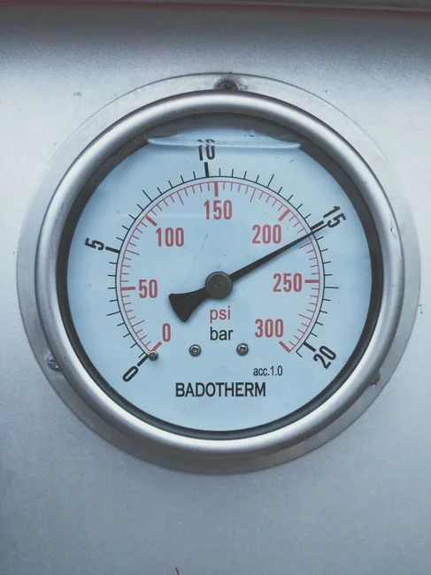
RO failure modes are directly linked to the operating mechanism, and correct diagnosis determines whether a system requires a scheduled CIP or an unscheduled element replacement.
- Fouling (biological, organic, colloidal). Symptom: flux decline with stable feed pressure. Cause: feed SDI above 5 or insufficient pretreatment. Fix: CIP at pH 11 followed by pH 2, then upgrade the multi-media pretreatment filter media.
- Scaling (CaCO₃, CaSO₄, SiO₂). Symptom: rising differential pressure across the last stage, typically from 0.5 bar baseline to above 2 bar. Cause: recovery set too high or antiscalant underdose. Fix: lower recovery by 5–10%, verify antiscalant injection, and run LSI adjustment.
- Oxidation damage. Symptom: sudden rejection drop of 2–5 percentage points. Cause: free chlorine breakthrough from exhausted carbon. Fix: replace carbon media and audit feed chlorine limits; this damage is irreversible if rejection has dropped below 90%.
- Membrane compaction. Symptom: gradual flux loss at constant pressure over 12–24 months. Cause: sustained operation above design pressure or temperature. Damage is irreversible, requires element replacement; for prevention, follow the industrial RO maintenance guide pressure limits.
- Mechanical failure. Symptom: pressure drop with no flux change. Cause: O-ring or vessel end-cap leak. Fix: O-ring replacement during scheduled shutdown, typically every 3–5 years per vessel.
For OPEX planning around membrane replacement, consumables, and energy, see the 2026 RO spare parts and OPEX breakdown.
Selection Checklist and Main Cost Drivers
Buyers who already understand how an RO system works still need a fixed decision list before freezing the P&ID. Start from feed chemistry and end-use purity, not from catalogue flow alone.
- Confirm feed SDI below 5, free chlorine below 0.1 mg/L, and turbidity below 1 NTU after pretreatment.
- Match operating pressure to feed TDS: 10–15 bar for brackish under 5,000 mg/L, 55–80 bar for seawater near 35,000 mg/L.
- Set recovery inside 65–85% for brackish or 40–50% for seawater unless a high-recovery study is complete.
- Specify CIP capability for pH 2 and pH 11–12 cleaning every 1–6 months.
- Budget ERDs on SWRO when specific energy above 3 kWh/m³ would dominate OPEX.
- Plan membrane replacement at 3–7 years for BWRO and 3–5 years for SWRO under compliant feed limits.
- Define concentrate disposition before purchase: discharge, brine recovery, or downstream biological polishing.
Main cost drivers are energy (especially SWRO without ERDs), membrane and cartridge change-outs, antiscalant dose at 1–5 mg/L, and CIP chemical use. Capital skews toward high-pressure pumps and FRP vessels when feed osmotic pressure is high.
Who This Is For / Who Should Look Elsewhere / Next Step
This guide is for plant engineers, EPC contractors, and procurement managers sizing BWRO or SWRO skids against a defined permeate spec. Look elsewhere if you only need particulate filtration or biological BOD removal without TDS reduction. For a duty-specific quote on membrane array, pretreatment, and CIP scope, submit feed data through our request-quote form.
Frequently Asked Questions
How much pressure does an RO system need?
Brackish RO typically needs 10–15 bar when feed TDS stays under 5,000 mg/L, while seawater RO needs 55–80 bar at about 35,000 mg/L TDS. Applied pressure must exceed concentrate osmotic pressure by at least 1–2 bar to keep net permeate flux. Undersizing the pump is the most common commissioning miss we see on brackish trains.
What does an RO system reject?
An RO membrane rejects 95–99% of dissolved salts, 99%+ of bacteria and viruses, and 90–99% of dissolved organics depending on molecular weight. Gases such as CO₂ pass freely, so decarbonation is often added upstream or between passes. Rejection for silica and boron is usually lower than for NaCl under the same conditions.
What is the difference between permeate and concentrate?
Permeate is the purified product water that passed through the membrane. Concentrate (reject or brine) is the feed fraction that did not pass and carries roughly 4–25× the original salt concentration depending on recovery. Disposition of concentrate often controls project feasibility more than permeate quality does.
How often do RO membranes need to be replaced?
RO membranes usually last 3–7 years on well-pretreated brackish feed and 3–5 years on seawater duty. Operating with feed SDI above 5 or free chlorine above 0.1 mg/L can shorten life to under 24 months. Track normalized flux and salt passage quarterly to plan change-outs before sudden failure.
Can an RO system run without pretreatment?
No. Feed SDI above 5 fouls membranes within weeks, and free chlorine above 0.1 mg/L oxidizes the polyamide thin-film composite layer, often irreversibly. Multi-media filtration, carbon for chlorine, 5-micron cartridge protection, and antiscalant dosing are minimum guards for industrial duty.