Why Peshawar's Climate Changes the Blowdown Problem
Peshawar's hot, semi-arid summers push any data center with evaporative cooling into high evaporation duty; blowdown therefore becomes the dominant wastewater stream by volume once cycles of concentration (CoC) are held to the conventional 4–6 range (Ecologix, 2025). The valley's groundwater and municipal supply are typically hard and silica-bearing, which is exactly the chemistry — silica plus CaCO₃ plus CaSO₄ — that caps conventional brackish reverse osmosis (BWRO) at 75–80% recovery (IDE Tech, 2026).
Discharge to sewer or surface water in Pakistan is regulated by the Pakistan Environmental Protection Act (PEPA) through provincial EPAs such as Khyber Pakhtunkhwa EPA; for a data center this means an industrial effluent consent with limits on TDS, temperature rise, heavy metals, and residual chlorine, not a generic municipal discharge (Ecologix, 2025). A 100 MW reference facility can use up to roughly 2 million liters of water per day, so even a mid-sized 5–10 MW colocation in Peshawar is sitting on tens of thousands of liters per day of recoverable cooling tower blowdown (CTBD) once WUE and CoC are worked through (IDE Tech, 2026).
The implication is that a Phoenix or Northern Virginia design basis cannot be copy-pasted into a Peshawar P&ID. Same physics of evaporation and mass balance, but the influent water is hotter, harder, and silica-richer, and the regulator is PEPA/KPK EPA, not the U.S. NPDES framework. The Ecologix reference puts the WUE benchmark at 1.8 L/kWh and the evaporative share at about 60% of total water use, with the remainder as blowdown (Ecologix, 2025). Use those numbers as the local sizing anchor, then layer the Peshawar-specific hydrology on top.
Cooling Tower Blowdown: Chemistry, Volume and Scaling Risk
CTBD at a Peshawar site is a brackish stream enriched with the three salts that govern RO scaling: silica, calcium carbonate, and calcium sulfate. Total dissolved solids (TDS) in the blowdown can reach about 2,000 ppm before operators intervene, and these are the species that cap conventional BWRO at 75–80% recovery (Ecologix, 2025; IDE Tech, 2026). On top of the salts, the blowdown carries residual treatment chemicals — molybdate-based corrosion inhibitors, biocides, phosphonate antiscalants — plus leached copper and zinc from the cooling loop, all sitting on a 30–40 °C thermal load (Ecologix, 2025; University of Georgia, 2026).
The blowdown ratio is 1 / (CoC − 1). At CoC 4, blowdown is 25% of make-up; at CoC 6, it falls to 20% — a 20% relative reduction, not the 50% that sustainability targets often assume (Genesis Water Technologies, 2025). Pushing CoC past 5–6 without addressing the chemistry usually stalls because scaling, microbiologically influenced corrosion (MIC), and fouling force operators back down (Genesis Water Technologies, 2025). That is the trap the Peshawar design has to design out, not around.
Two further risks are specific to the Peshawar hydrology. First, silica in Peshawar valley groundwater sits in a range where RO antiscalants only buy a few points of recovery before saturation forces a different architecture. Second, hotter ambient temperatures push the tower's approach and range tighter, so the blowdown arrives at the treatment train already at 30–40 °C, which shortens the window for any biological stage and increases the cooling duty on the RO feed (Ecologix, 2025; University of Georgia, 2026).
Reference Process Train for a Peshawar Data Center
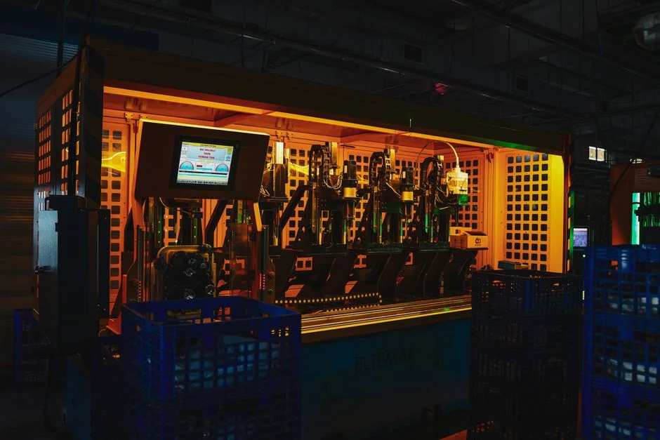
The train is sequenced so each stage protects the next. Start with coarse screening and a multi-media pretreatment filter (sand plus anthracite plus garnet) sized to drop turbidity and protect downstream RO, with SDI₁₅ held below the membrane limit (Ecologix, 2025). Stage 2 is either a side-stream softening unit in Na-form ion exchange or, more commonly at this scale, a PLC-controlled antiscalant and biocide dosing skid dosed to keep CaSO₄ and CaCO₃ below scaling thresholds; the Langelier Saturation Index (LSI) on the RO feed is held between −0.5 and +0.5 (Ecologix, 2025).
Stage 3 is the main separation step: a industrial RO system with 75–95% recovery operating at a conservative 75–80% local recovery. Permeate at this point is already suitable as cooling-tower make-up (IDE Tech, 2026). Where the project targets >70% overall reuse, Stage 4 wraps the RO in a high-recovery architecture — either a closed-loop or dynamic batch RO with controlled silica and CaSO₄ precipitation — to push overall recovery toward 90–95% (IDE Tech, 2026; Ecologix, 2025). Stage 5 is cartridge polishing down to 5 µm followed by chemical-free UV disinfection on the permeate, with an on-site ClO2 generator for biofilm control available where the cooling loop needs an oxidizing residual (IDE Tech, 2026; Ecologix, 2025).
Stage 6 handles the concentrate. For partial-reuse, route the brine to neutralization and a sludge dewatering filter press for the brine line; for zero-liquid discharge (ZLD), add a brine concentrator and crystallizer as a separate CAPEX line (Saltworks Technologies, 2026; Ecologix, 2025). The 75–80% BWRO ceiling is a property of the chemistry, not a vendor limit — and the high-recovery stage exists to break that ceiling without inheriting a fragile, chemical-intensive operation (IDE Tech, 2026).
Parameter Table: Flows, Recoveries and Treated-Water Targets
The table below is the kind of artifact a project engineer can drop into a design basis. Flows are scaled from the Ecologix WUE benchmark of 1.8 L/kWh and the 60% evaporative / 40% blowdown split (Ecologix, 2025), and the CoC 4 vs CoC 6 blowdown fractions (25% vs 20% of make-up) come from Genesis Water Technologies (2025).
| Stage | Design flow per 1 MW IT load | Local recovery | Overall recovery (with high-recovery stage) | Key influent / effluent parameters | Target reuse stream |
|---|---|---|---|---|---|
| 1. Multi-media filtration (sand + anthracite + garnet) | ~0.9 L/s (≈15 GPM) | n/a (particulate removal) | n/a | Turbidity in: variable; SDI₁₅ out: below RO limit | RO feed |
| 2. Side-stream softening or antiscalant dosing | ~0.9 L/s (≈15 GPM) | n/a | n/a | LSI in: −0.5 to +0.5; hardness, silica, Fe, Mn per raw-water analysis | RO feed |
| 3. Brackish RO (BWRO) | ~0.9 L/s (≈15 GPM) | 75–80% | 75–80% | TDS in: up to ~2,000 ppm; TDS out: <500 ppm | Cooling-tower make-up |
| 4. High-recovery RO upgrade (closed-loop or dynamic batch) | Same RO skid, recirculated | Step up to ~90–95% overall | 90–95% | Silica: controlled precipitation; CaSO₄: below saturation | Cooling-tower make-up |
| 5. Cartridge polish (5 µm) + UV or ClO₂ | Permeate side | n/a | n/a | UV dose or residual ClO₂ per local permit | Cooling-tower make-up |
| 6. Brine neutralization + sludge dewatering (or crystallizer for ZLD) | Concentrate side | n/a | n/a | Concentrate volume = make-up × (1 − overall recovery) | Cake to disposal; permeate to make-up (if ZLD) |
For a 5–10 MW colocation, the practical modular envelope lands in the 100–300 GPM range once the WUE benchmark, the 60% evaporative share, and a CoC of 4–6 are applied to the site IT load (Ecologix, 2025; Genesis Water Technologies, 2025).
Partial Reuse vs ZLD: Decision Framework for Peshawar
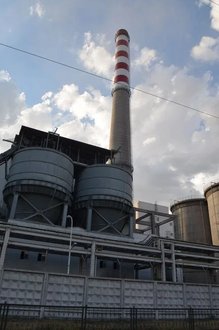
Whether a Peshawar site can stop at partial reuse or has to push to ZLD is set by three inputs: the PEPA/KPK EPA discharge consent, the local WWTP capacity, and the operator's water-stewardship target. If the consent is achievable — TDS below the local limit, ΔT under 5 °C, heavy metals within limits, and a municipal WWTP that will accept the residual — closed-loop cooling with on-site CTBD reuse at 50–70% recovery is the cost-effective default, and make-up can drop to less than 5% annually (Ecologix, 2025). If the discharge path is constrained, push to high-recovery RO at about 90–95% and add brine concentration or crystallization as a separate CAPEX line (IDE Tech, 2026; Saltworks Technologies, 2026).
Right-size to facility scale. A 5 MW colocation rarely justifies hyperscale RO; a modular 100–300 GPM blowdown treatment train is the practical fit, and hyperscale-grade technology typically fails economically at smaller facilities because CAPEX per gallon treated runs 3–4× higher without the operating-staff depth (Genesis Water Technologies, 2025). On the sanitary side, an MBR integrated wastewater treatment unit handles the small, intermittent sanitary load and can be shared between the data center and any on-site admin block.
Avoid the chemical-intensity trap. Pushing CoC with ever-heavier phosphonate and biocide dosing raises chemical cost and makes downstream CTBD reuse harder, not easier — the dissolved-solids load in the blowdown climbs with the dose, and the RO front-end has to work harder (Genesis Water Technologies, 2025).
| Decision input | Partial reuse (50–70% recovery) | High-reuse / near-ZLD (90–95% recovery) | Full ZLD (crystallizer) |
|---|---|---|---|
| PEPA / KPK EPA consent achievable? | Yes — fits the default path | Marginal — usually overkill if consent is clean | Required if no liquid discharge is permitted |
| Local WWTP capacity for residual | Available | Constrained or unavailable | Not available or hyperscaler water-positive commitment |
| CAPEX profile (qualitative, 5–10 MW site) | Low six figures USD | Mid six figures USD | Higher; thermal stage adds OPEX |
| OPEX driver | Chemical cost, RO membrane life | Antiscalant, energy, membrane cleaning | Thermal energy, crystallization |
| Typical fit at 5–10 MW | Default | If discharge path is constrained | Rare; only where ZLD is mandated |
Cost Band and Procurement Checklist for a Peshawar Site
For a 15 MW reference site, a partial-reuse modular system typically lands in the low six figures USD, with simple payback in the 3–5 year range once wastewater, discharge, and water-stress costs are fully accounted (Genesis Water Technologies, 2025). For a 5–10 MW Peshawar colocation, the practical envelope is the modular 100–300 GPM train — full hyperscale RO is rarely the right answer at this scale, and the cost band is best confirmed against a site-specific quotation rather than copied from another region (Genesis Water Technologies, 2025).
Inputs to lock down before supplier selection: raw-water analysis (TDS, hardness, silica, Fe, Mn), CTBD analysis (TDS, scaling indices, residual biocides), peak IT load, target WUE and CoC, PEPA consent limits, available plot area, power availability, and operator skill level (Genesis Water Technologies, 2025; Ecologix, 2025). Plan for biofilm control that does not contaminate the reuse stream — UV or on-site ClO₂ generation is preferred over persistent oxidizing biocides that pass through RO and re-enter the cooling loop (Ecologix, 2025). For membrane and parts sourcing, keep an eye on RO/UF membrane and filter element supply and water treatment parts, valves, and media lead times into Pakistan, which directly affect the construction schedule.
For a deeper dive on a comparable urban site, the 2026 NYC data center blowdown engineering guide covers the high-TDS mains-water case, while the 2026 Athens data center blowdown guide covers the Mediterranean climate angle. For facility-level water reduction outside the data center, the 2026 industrial water-reduction engineering guide is a useful cross-reference.
Frequently Asked Questions
What is the dominant wastewater stream at a Peshawar data center?
Cooling tower blowdown (CTBD), not sanitary waste. In evaporative systems, about 60% of intake water is lost to evaporation and the remainder is purged as blowdown at cycles of concentration typically held to 4–6, so CTBD dominates the site liquid waste by volume (Ecologix, 2025).
Can a 5 MW colocation in Peshawar afford a high-recovery RO system?
A 5 MW site is at the lower bound where hyperscale RO is economic, and a modular 100–300 GPM partial-reuse train is the practical fit; hyperscale-grade technology tends to fail economically at this scale because CAPEX per gallon treated runs 3–4× higher than at 100+ MW sites (Genesis Water Technologies, 2025). Request a site-specific quotation against the raw-water analysis, the CTBD analysis, and the target WUE before sizing the system.
What discharge limits apply to a data center in Peshawar?
Discharge is regulated by the Pakistan Environmental Protection Act (PEPA) through provincial EPAs, with Khyber Pakhtunkhwa EPA as the local consent authority for a Peshawar site. The consent sets limits on TDS, temperature rise (commonly referenced against a 5 °C ΔT), residual chlorine, and heavy metals, so the design basis must be built around the local consent values rather than a generic municipal discharge (Ecologix, 2025).
Is ZLD required, or is partial reuse enough?
Partial reuse at 50–70% recovery is the cost-effective default where the PEPA/KPK EPA consent is achievable and the local WWTP will accept the residual. ZLD or near-ZLD is only justified when the discharge path is constrained, the hyperscaler has a water-positive commitment, or liquid discharge to the environment is not permitted (IDE Tech, 2026; Ecologix, 2025; Saltworks Technologies, 2026).