
What Counts as Ultrapure Water in a 2026 UK Fab
For a UK semiconductor or advanced-electronics fab in 2026, ultrapure water (UPW) is defined by five binding axes: resistivity of 18.2 MΩ·cm at 25°C, total organic carbon (TOC) below 1 µg/L, dissolved silica at or below 0.5 µg/L, particles under 1 per mL above 0.05 µm, and bacteria below 1 CFU per 1,000 mL sample at the point of distribution (POD) (per ASTM D5127-13 Table 1, Type E-1.2). To anchor the difference: UK mains water typically measures 0.005-0.05 MΩ·cm, single-pass RO permeate reaches 0.1-1.0 MΩ·cm, and only a fully polished loop sustains 18.2 MΩ·cm (S3). The governing documents are SEMI F63 (the fab-purchasing specification for UPW) and ASTM D5127-13 (the standard guide covering Types E-1 through E-4 by device linewidth); the IRDS roadmap is the forward-looking reference for sub-2 nm nodes where TOC targets are dropping below 0.5 µg/L (S4).
The linewidth split matters for any UK URS. E-1.1 covers 0.35-0.25 µm, E-1.2 covers 0.18-0.09 µm, and E-1.3 covers 0.065-0.032 µm — each step tightens TOC, silica, and metals limits per ASTM D5127-13 Table 1 (S4). A fab in the Newport, Manchester, or Cambridge cluster mixing legacy 0.18 µm lines with new sub-32 nm tools will realistically run dual POD loops, not a single blended spec. The single most common audit finding in UK fabs is that the spec is quoted at the make-up stream rather than at the POD — D5127-13 §4.2 makes clear the limits apply at the POD, and a 0.1-0.3 MΩ·cm drop between make-up and POD is normal during a polishing stage trip (S4). For consenting context, abstraction and discharge permits are issued by the Environment Agency under the Environmental Permitting (England and Wales) Regulations 2016, and any RO concentrate or resin-regeneration waste must be addressed in that permit scope (see also the semiconductor wastewater treatment design guide and the 20-year UPW lifecycle cost guide).
UPW Quality Parameters vs Device Linewidth
ASTM D5127-13 Table 1 is the only document a UK Environment Agency reviewer and a procurement director both recognise, and it ties every limit to a device-linewidth band. The headline numbers at 25°C: resistivity 18.1 MΩ·cm (E-1), 18.2 MΩ·cm (E-1.1/E-1.2/E-1.3), 16.5 MΩ·cm (E-2), 12 MΩ·cm (E-3) and 0.5 MΩ·cm (E-4). TOC falls from 5 µg/L at E-1, to 2 µg/L at E-1.1, to 1 µg/L at E-1.2 and E-1.3, before relaxing to 50 µg/L (E-2) and 300 µg/L (E-3). Dissolved silica is 3, 1, 0.5 and 0.5 µg/L across E-1 through E-1.3; total silica 5, 3, 1, 0.5 µg/L respectively. Bacteria limits move from 5 CFU/100 mL (E-1) to 1 CFU/1,000 mL (E-1.2) and 3 CFU/100 mL at E-1.1 (S4).
Trace metals measured by ICP-MS sit in the 0.001-0.05 µg/L band for E-1.2/E-1.3 — for example Cu 0.002, Fe 0.002, Na 0.005, Ca 0.002 µg/L — which is below the detection limit of most online instrumentation and forces offline lab cross-checks (S4). Particle counts per litre at E-1.2 are ≤200 above 0.05 µm, ≤100 in the 0.05-0.1 µm range, dropping to <1 above 1.0 µm; SEMI F63 expresses the same envelope for purchasing specifications. Temperature must be held to ±1 K with a gradient under 0.1 K per 10 minutes at the POD to prevent wafer-scale thermal shock during immersion or spray cleaning. Next-generation 3 nm and 2 nm logic nodes are already pushing TOC below 0.5 µg/L ahead of any formal revision to D5127, so specify the next-generation envelope in the URS even if the standard has not caught up (S3).
| Parameter | E-1 (1.0-0.5 µm) | E-1.1 (0.35-0.25 µm) | E-1.2 (0.18-0.09 µm) | E-1.3 (0.065-0.032 µm) |
|---|---|---|---|---|
| Resistivity at 25°C (MΩ·cm) | 18.1 | 18.2 | 18.2 | 18.2 |
| TOC (µg/L) | 5 | 2 | 1 | 1 |
| Silica — dissolved (µg/L) | 3 | 1 | 0.5 | 0.5 |
| Silica — total (µg/L) | 5 | 3 | 1 | 0.5 |
| Bacteria (CFU/sample) | 5 / 100 mL | 3 / 100 mL | 1 / 1,000 mL | N/A |
| Particles >0.05 µm (per L) | 500 | 1,000 | 200 | N/A |
| Cu / Fe / Na by ICP-MS (µg/L) | 0.05 | 0.02 | 0.002 / 0.002 / 0.005 | 0.001 |
| Temperature stability | ±1 K | ±1 K | ±1 K | ±1 K |
Piping extractables, joint count, and dead-leg volume also belong in the spec — see the UPW piping long-term cost guide for the extractables envelope and the 20-year cost case for high-purity PVDF and PFA loops.
The Multi-Stage UPW Treatment Train
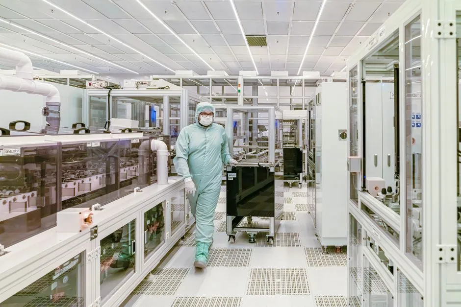
A 2026 fab UPW system is six engineering stages run continuously, not a single pass. Stage 1 pretreatment takes UK mains water (100-300 mg/L hardness as CaCO₃, 0.2-0.8 mg/L free chlorine, 2-6 mg/L seasonal TOC) through a multi-media pretreatment filter to under 5 µm, an activated-carbon block for chlorine and chloramine removal, and an industrial water softener reducing hardness to under 1 ppm; UK hardness makes the softener non-optional (S3). Stage 2 primary industrial RO system achieves 95-99% rejection, taking TDS from 200-500 ppm down to 5-25 ppm at 300-400 psi with a 3-5 year membrane life (S3). Stage 3 is either a second RO pass or a continuous electrodeionization module polishing to above 2 MΩ·cm at 90%+ recovery without acid/caustic regeneration.
Stage 4 is dual-wavelength 185 nm / 254 nm UV steriliser treatment: 185 nm drives organics to CO₂ and H₂O to land TOC below 1 µg/L, 254 nm destroys ozone and controls microbial counts, with lamp life of 9,000-12,000 hours (S3). Stage 5 is a hollow-fibre ultrafiltration system at 0.01-0.03 µm cut and around 10,000 MWCO to catch particles, colloids, and bacterial fragments — periodic pressure-hold integrity testing is mandatory because particle monitoring alone will not catch a 0.5 µm pinhole leak in a hollow-fibre module (IEEE ASMC 2016, S1). Stage 6 is final polishing: non-regenerable mixed-bed ion exchange to 18.2 MΩ·cm, membrane degasification, and a 0.2 µm final filter at the POD. The distribution loop recirculates at 1-2 m/s to prevent biofilm and particle re-deposition, with sub-loop temperature control at the tool.
| Stage | Block | Performance | Operating envelope |
|---|---|---|---|
| 1 — Pretreatment | MMF + carbon + softener | Turbidity <5 µm; Cl₂ 0; hardness <1 ppm | SDI <3 to RO; COSHH-compliant dosing |
| 2 — Primary RO | Thin-film composite | 95-99% rejection; TDS 5-25 ppm | 300-400 psi, 3-5 yr membrane life |
| 3 — Polishing | 2nd-pass RO or EDI | >2 MΩ·cm continuous; 90%+ recovery | No acid/caustic regen for EDI |
| 4 — UV oxidation | 185 nm + 254 nm | TOC <1 µg/L; microbial control | 9,000-12,000 h lamp life |
| 5 — Ultrafiltration | PVDF hollow-fibre | <0.01 µm cut; ~10,000 MWCO | Pressure-hold integrity test per IEEE ASMC 2016 |
| 6 — Final polish + POD | Mixed-bed + degas + 0.2 µm | 18.2 MΩ·cm at POD | 1-2 m/s loop; ±1 K control |
UK Feedwater and Pretreatment Considerations
UK municipal water is the design basis nobody else in the SERP talks about. Hardness ranges 100-300 mg/L as CaCO₃, free chlorine 0.2-0.8 mg/L (with monochloramine in some regions), TDS 50-500 mg/L, and seasonal TOC of 2-6 mg/L — these bands drive softener sizing, carbon bed volume, and the antiscalant dose into the RO feed (S3). The Environment Agency issues abstraction licences under the Environmental Permitting (England and Wales) Regulations 2016, and new fabs in drought-stressed south-east England (where several compound semiconductor sites are located) face progressively tighter abstraction limits; planning the feedwater blend around the consent envelope is now as important as the polishing train.
RO membranes need a Silt Density Index under 3 to deliver their 3-5 year service life; an SDI of 5 or more will foul thin-film composite membranes inside 12-18 months and is one of the most common causes of premature RO replacement observed in the field (S3). Antiscalant dosing and antifoam control sit inside the pretreatment scope and trigger COSHH-compliant chemical handling per HSE guidance — a chemical dosing skid with bunded containment and dosing interlocks is now standard in UK fabs. A borehole or rainwater-harvest blend for non-UPW process water (cooling tower make-up, scrubber feed, CCTV rinse) can lower the mains demand and the consenting risk, but it cannot feed the UPW loop without full polishing.
Component Selection: RO, EDI, UV and UF
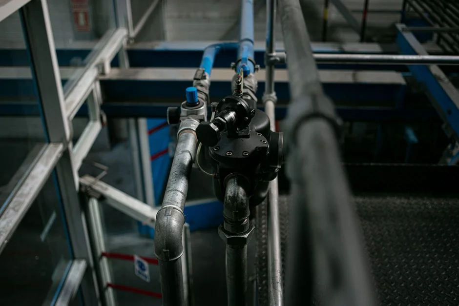
The component matrix below is what a UK RFQ usually gets wrong. Single-pass RO is acceptable for legacy 0.5 µm lines, but sub-32 nm nodes need double-pass RO because the first pass leaves an ionic load that a single EDI block cannot fully polish to 18.2 MΩ·cm without periodic resin regeneration (S3). EDI versus mixed-bed is a consenting decision as much as a chemistry decision: EDI removes the acid/caustic regeneration waste stream that a mixed-bed generates, which simplifies the Environment Agency discharge consent, but a mixed-bed still wins on the very top of the TOC and silica envelope, so a hybrid (EDI + polishing mixed-bed) is common at Type E-1.2 fabs.
UV wavelength choice is non-negotiable. 185 nm is required to drive TOC below 1 µg/L, 254 nm is required to destroy residual ozone and control microbial counts, and most fabs run both lamps in series inside a single skid (S3). For UF, specify PVDF hollow-fibre at 0.01-0.03 µm cut, and write the periodic pressure-hold integrity test into the sub-vendor scope — particle monitoring alone will not catch a 0.5 µm pinhole leak and that is the exact point made in the IEEE ASMC 2016 quality-control paper (S1). POD loop piping is high-purity PVDF or PFA with extractables below 0.1 µg/L; the cost-of-ownership case for PVDF is set out in the UPW piping long-term cost guide. On-line monitoring needs redundant sensors at the make-up stream and the POD, measuring resistivity, TOC, particles, dissolved oxygen, and silica — the make-up stream is for the operator, the POD is for the regulator.
| Decision | Option A | Option B | Selection rule for UK fabs |
|---|---|---|---|
| RO configuration | Single-pass RO | Double-pass RO | Sub-32 nm node: double-pass mandatory (S3) |
| Ion exchange | EDI | Mixed-bed (regenerable) | EDI for EA consent simplicity; mixed-bed for tightest TOC/silica |
| UV wavelength | 185 nm only | 185 nm + 254 nm series | Both in series for E-1.2 (S3) |
| UF membrane | PES flat-sheet | PVDF hollow-fibre | PVDF 0.01-0.03 µm + pressure-hold test (S1) |
| POD piping | PVC-C / PP | High-purity PVDF / PFA | PVDF/PFA only; extractables <0.1 µg/L |
Spare RO and UF membrane elements should be held in UK service-van stock for 24/7 uptime; the POD spare and the EDI module spare typically ride on a 4-hour engineer response contract, especially for fabs running E-1.2.
Energy, Water Recovery and Operating Cost
UPW is energy-intensive: 3-7 kWh per 1,000 gallons produced, which on a 2-4 MGD fab is a multi-megawatt load and supports a strong case for heat-recovery payback (S3). The municipal-to-UPW ratio is 1,400-1,600:1,000 — meaning 25-40% of feedwater is lost in purification and must be either discharged (with consent) or reused. Industry water recycling currently runs 65-75%, with 85-90% targets for next-generation fabs, which forces RO concentrate and rinse-water reclaim into the design scope rather than treating them as wastewater.
Annual water OPEX in the UK lands in the £2M-£8M per-fab band depending on capacity and local water tariffs, so a 10 percentage-point swing in recovery is a multi-hundred-thousand-pound line item. Consumable life drives the spares and service scope: 3-5 years for RO membranes, 9,000-12,000 hours for UV lamps, 5-10 years for EDI modules under controlled feedwater (S3). The full 20-year lifecycle model — CAPEX, membrane replacement, energy, chemical, and decommissioning — is in the 20-year UPW lifecycle cost guide. Replacement membrane elements are the largest single OPEX line in years 4-6 of the loop.
On-Line Monitoring, Validation and Audit Readiness
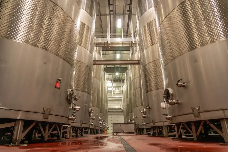
An UPW system is only as auditable as its data historian. Continuous on-line instrumentation at the POD must include resistivity, TOC, dissolved oxygen, silica, conductivity, and laser particle counters, with alarm setpoints locked to ASTM D5127-13 Type E-1.2 values rather than the make-up spec (S4). For UF, particle monitoring alone is insufficient — periodic pressure-hold integrity testing is the only way to detect pinhole leaks below the optical counter's resolution, and IEEE ASMC 2016 makes this point explicitly (S1).
Data retention needs to be specified in writing: trend at least 12 months at 1-minute resolution for SEMI and customer audits, and 24 months where the Environment Agency has a water-use or discharge condition. Calibration cadence should be quarterly for on-line TOC, six-monthly for offline ICP-MS checks, and an annual third-party cross-check using a UKAS-accredited laboratory. The alarm and interlock philosophy is the bit that protects the wafer: out-of-spec POD water must divert to a non-process drain automatically and trigger a tool-side interlock so that no further wafers enter the affected bath. Spare valves, sensors, and resin cartridges are kept under a 4-hour engineer response contract for the 24/7 uptime envelope a fab needs (see UPW spare parts and consumables).
Frequently Asked Questions
What resistivity, TOC and silica limits apply to a UK sub-32 nm fab in 2026?
For devices at 0.18-0.09 µm (Type E-1.2) and 0.065-0.032 µm (Type E-1.3), the binding limits at the point of distribution are 18.2 MΩ·cm at 25°C, TOC 1 µg/L, dissolved silica 0.5 µg/L, and bacteria 1 CFU per 1,000 mL sample, per ASTM D5127-13 Table 1. IRDS roadmap fabs are already targeting TOC under 0.5 µg/L for 3 nm and 2 nm logic.
Is single-pass RO sufficient to hit 18.2 MΩ·cm, or do I need double-pass?
Single-pass RO can deliver about 0.1-1.0 MΩ·cm permeate; to reach 18.2 MΩ·cm you need either double-pass RO with EDI polishing or double-pass RO with a non-regenerable mixed-bed. Sub-32 nm nodes effectively mandate double-pass because the ionic load from a single pass overwhelms the polishing block.
Why does UK feedwater change my pretreatment design versus a US or Taiwan fab?
UK municipal water typically runs 100-300 mg/L hardness as CaCO₃, 0.2-0.8 mg/L free chlorine, and 2-6 mg/L seasonal TOC. That makes the softener, the carbon bed, and the antiscalant dose larger than in lower-hardness regions, and it forces the RO feed SDI below 3 to protect the 3-5 year membrane life that the spec quotes.
How is a 185 nm / 254 nm UV skid sized for TOC below 1 µg/L?
The 185 nm lamp drives TOC reduction by breaking organics to CO₂ and H₂O; the 254 nm lamp destroys residual ozone and controls microbial counts. Both are run in series, sized at roughly 1-2 kW per 10 m³/h of polished flow, with lamp life 9,000-12,000 hours and a UV-intensity monitor to trigger replacement.
What monitoring proves to the Environment Agency that we are on spec 24/7?
On-line resistivity, TOC, dissolved oxygen, silica, and particle counters at the POD, trended at 1-minute resolution and retained for at least 12-24 months. UF integrity needs a separate pressure-hold test log because particle counters will not catch sub-micron pinhole leaks (IEEE ASMC 2016, S1). Cross-checks against a UKAS-accredited ICP-MS lab should run at least six-monthly.
How much of our UPW feed can we realistically recycle?
Industry runs 65-75% reuse today, with 85-90% targets for next-generation fabs, driven by RO concentrate and rinse-water reclaim. The municipal-to-UPW ratio of 1,400-1,600:1,000 means every percentage point of recovery reduces both abstraction volume (which the Environment Agency limits) and operating cost (S3).