Why Semiconductor Wastewater Defies Single-Process Design
A 2026 semiconductor wastewater treatment system is built as a segregated, multi-stage train — fluoride precipitation plus coagulation, two-stage MBBR/MBR for organics and TMAH, RO polishing and an optional ZLD loop — sized to absorb daily swings in HF, CMP slurry, IPA and ammonia loads. Average-load designs fail because the influent is not one stream; it is six or seven streams with different pH, redox, and organic character that meet in the equalisation tank.
Wafer fabrication runs through eight steps — wafer manufacturing, oxidation, photolithography, etching, deposition and ion implantation, metallization, EDS, and packaging — and the wafers pass through more than 1,000 clean-room cleaning steps in between (Sim et al., 2023, citing Tsai et al., 2002). Each step donates a different contaminant family: HF and NH₄F from etching; silica, alumina and ceria nanoparticles plus Cu from chemical mechanical polishing; TMAH and photoresist solvents from lithography; IPA and VOCs from rinsing; and HNO₃, H₂SO₄ and H₂O₂ from cleaning. The volume signal is climbing with the chemistry signal: Korean national data show wastewater generation rising 19.3% and discharge rising 19.0% between 2010 and 2019 (Sim et al., 2023, citing Statistics Korea). On top of that, the same fab produces streams that can treat each other — a "waste control by waste" principle in which silica-bearing CMP wastewater can act as a coagulant for fluoride-bearing HF wastewater (SSRN 4009571). That opportunity is only real if the streams are kept apart until the right mixing step.
Mapping Variable Waste Chemistry: A Stream-by-Stream Characterisation
The design starts with an influent matrix, not a single average. Stream segregation is what makes the rest of the train controllable. The table below summarises typical stream envelopes drawn from DAS Environmental Experts' semiconductor contaminant list (HNO₃, H₂SO₄, HF, NH₃, H₂O₂, IPA plus particles) and from published process data; values are typical 95th-percentile envelopes for a 300 mm wafer fab.
| Stream | pH | F⁻ (mg/L) | NH₃-N (mg/L) | COD (mg/L) | TSS (mg/L) | SiO₂ / Cu | Swing behaviour |
|---|---|---|---|---|---|---|---|
| HF spent etch | 1–3 | 200–920 | 5–50 | 50–200 | 10–50 | low / low | Batch dumps from etcher PM cycles |
| CMP oxide slurry | 9–11 | 5–20 | 10–40 | 500–2,000 | 500–5,000 | SiO₂ 200–800 mg/L / low | Swings with wafer lot mix |
| CMP Cu slurry | 6–9 | 5–20 | 10–40 | 300–1,500 | 200–2,000 | low / Cu 20–100 mg/L | Cu chelator/BTA present |
| Photoresist developer (TMAH 2.38%) | 13–14 | 0–5 | 5–30 | 1,000–4,000 | 50–200 | low / low | Batch-dumped from litho track |
| IPA rinse | 6–9 | 0–5 | 5–20 | 3,000–10,000 (VOC) | 10–50 | low / low | Solvent peaks from dryer maintenance |
| General acidic | 1–4 | 10–100 | 20–80 | 100–500 | 20–100 | low / trace | Continuous, low swing |
| General alkaline | 9–12 | 0–20 | 20–80 | 200–800 | 20–100 | trace / low | Continuous, low swing |
| UF backwash | 6–8 | 0–10 | 5–20 | 50–300 | 50–500 | SiO₂ 20–100 mg/L / low | Pulsed, low volume |
The HF envelope is the driver: concentrated streams can reach ~920 mg/L F⁻ (HydropureWater HF guide, 2025-08), and that number sets the precipitation tank size, the CaCl₂ storage, and the safety bund. TMAH and IPA are batch-driven, not continuous — TMAH from photoresist developer dumps, IPA from dryer drain peaks — so the design load envelope should be expressed as the 95th-percentile batch over a representative production week, not as a daily mean. The envelope concept carries through the rest of the train.
Reference Treatment Train Architecture for 2026 Fabs
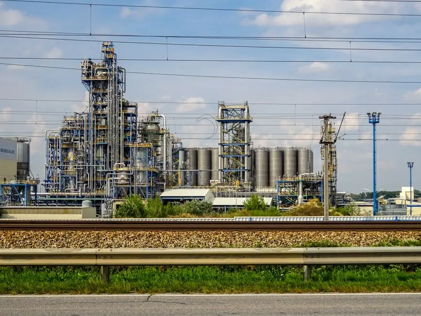
The train is segmented so that variable chemistry is absorbed at each stage rather than carried into the next one. The sequence is: source segregation into 4–6 sub-streams; equalisation and pH conditioning; fluoride precipitation with CaCl₂ or alum; coagulation and DAF for CMP particles and metals; anoxic + aerobic MBBR for COD, TMAH and NH₃-N; MBR polish; multi-media filter; RO; and an optional ZLD brine loop fed from the RO concentrate.
The biological backbone follows the DAS Environmental Experts reference train: one mixing/balancing tank with pH adjustment, nutrient dosing and H₂O₂ catalysis; two aerobic MBBRs in series for COD and nitrification; one anoxic MBBR for denitrification; flotation for solids separation; and sludge dewatering (DAS, 2024). MBBR is preferred over conventional activated sludge for fab duty because the carrier-protected biofilm holds a high sludge age and tolerates the TMAH and IPA peaks that would wash out a floc-based system. A MBR polishing stage is added downstream of the MBBR when the downstream RO needs a stable, low-SDI feed. A coarse mechanical bar screen protects the head of the train from plastic and packaging debris, and the upstream biological/chemical train is described in greater depth in a 2026 microelectronics wastewater design deep dive.
RO is placed last, not first, because oxidants, silica and F⁻ breakthrough shorten membrane life. The permeate is split by end-use: cooling-tower and scrubber makeup (Tier 1, lower purity, lowest incremental treatment), process rinse water (Tier 2), and UPW feed polishing via RO/EDI (Tier 3, highest purity). Each tier carries a different water-quality spec, so the design is not one RO — it is RO + optional EDI sized for the highest-purity end-use.
Unit-Process Parameter Windows for Variable Loads
The table below gives parameter windows the engineer can drop into a P&ID or datasheet. The numbers are engineering ranges drawn from the DAS MBBR reference, the Sim et al. (2023) review, and standard practice for fluoride, MBR and RO duty.
| Unit operation | Parameter | Window | Notes |
|---|---|---|---|
| Fluoride precipitation | pH / CaCl₂ dose / HRT | pH 6–8; CaCl₂ 2–5× stoichiometric of F⁻; HRT 30–60 min in clarifier | Expected residual <10 mg/L F⁻; polish with activated alumina or ion-exchange "police filter" for hard spikes |
| Coagulation / DAF | Coagulant / flocculant / surface loading | Alum or PAC 50–200 mg/L + anionic flocculant 0.5–2 mg/L; 5–15 m/h | Removes >90% CMP silica and most colloidal metals; see DAF stage for CMP slurry and coagulated metals |
| MBBR (COD + TMAH) | HRT / MLVSS / DO / F/M | Aerobic HRT 6–12 h; MLVSS 3,000–5,000 mg/L; DO 2–4 mg/L; F/M 0.1–0.3 kg COD/kg MLVSS·d | Anoxic zone HRT 2–4 h for denitrification upstream of aerobic |
| MBR polish | Flux / membrane / effluent | 10–20 L/m²·h on 0.1 µm PVDF; TSS <5 mg/L; turbidity <1 NTU | Protects downstream RO from biomass and colloids |
| Multi-media filter | Media / loading | Anthracite + sand + garnet; 10–15 m/h | Acts as a multi-media filter protecting the RO membranes against residual TSS spikes |
| RO | Recovery / feed SDI / antiscalant | 70–90% recovery; feed SDI <3; antiscalant 1–5 mg/L | Concentrate routed to brine concentrator if ZLD is selected; RO polishing for fab reuse sets reuse-tier quality |
| ZLD loop | Brine TDS / crystalliser | Brine concentrator to 8–12% TDS; MVR crystalliser for zero liquid discharge | Justified by local water-stress tariff + disposal cost + reuse demand; see decision framework below |
Chemicals are metered in by PLC-controlled chemical dosing skids tied to the online sensors in the next section, so the doses in the table are targets, not fixed setpoints.
Variable-Chemistry Control: Buffers, Sensors and Stream-Segregation Logic
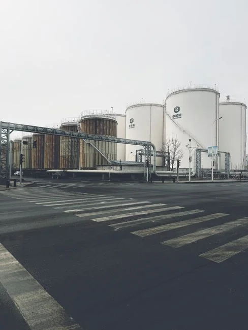
Equalisation tanks sized for 8–24 h HRT flatten the TMAH and IPA batch peaks before they reach the biology; shorter HRTs let those peaks through and trip the nitrifiers. The tank feeds online pH, conductivity, F⁻, NH₃-N and TOC analysers with PLC feedback to the caustic, acid and coagulant dosing skids (HydropureWater field data, 2026). Setpoint windows: F⁻ in biological feed <50 mg/L, NH₃-N <200 mg/L, pH 6.5–8.5; exceeding any of these diverts flow to a dedicated chemical-treatment loop rather than letting it shock the biofilm.
Stream-routing logic exploits the "waste control by waste" principle (SSRN 4009571): the fluoride-lean, silica-rich CMP stream is metered into the fluoride-bearing HF equalisation line as a partial coagulant, replacing a fraction of the fresh CaCl₂ or alum. A conductivity- and TOC-based router also sends the IPA-rich stream around the biology to an AOP or air-stripper, and the TMAH-rich developer dump is paced into the MBBR feed over 4–6 h rather than dumped in a single slug. The same PLC-controlled chemical dosing skid handles coagulant, polymer and pH correction; the controller logic is the same hardware, the recipe is what changes by stream.
Reuse vs ZLD: Decision Framework and 2026 Cost Logic
The choice between reuse-only and reuse-plus-ZLD is driven by three numbers: local freshwater tariff plus disposal cost, the percentage of treated water that can be reused in-process, and the regulator's position on brine discharge. Reuse tiers map to treatment cost: Tier 1 cooling-tower and scrubber makeup (lowest incremental cost), Tier 2 process rinse water, Tier 3 UPW feed (RO/EDI, highest cost). The table below summarises the qualitative tipping point.
| Driver | Reuse-only train | Reuse + ZLD loop |
|---|---|---|
| Water-stress tariff | Low to moderate | High (>$1–2/m³ combined) |
| Direct discharge option | Permit available | Banned or restricted |
| Reuse demand | <25–30% of treated flow | >25–30% of treated flow, or >70% recovery required |
| Brine disposal cost | Tolerable | High or unavailable |
| Order-of-magnitude CAPEX | Lower (RO/EDI train only) | Higher (brine concentrator + MVR crystalliser) |
Order-of-magnitude CAPEX framing: an RO/EDI reuse line is typically a fraction of a full ZLD crystalliser loop; the ZLD loop is justified mainly where direct discharge is banned, freshwater cost is high, or the site has a corporate water-stewardship target that mandates closed loop. The practical design move is to build the upstream biological/chemical train to be ZLD-ready — low fouling, low silica, low residual organics in the RO feed — even if ZLD is not built in year 1; that way the brine concentrator and MVR crystalliser can be added without reworking the front end. The EDI stack and the RO/UF membrane elements for the reuse train should be specified to the windows given in the parameter table, and the recovery and antiscalant logic should be aligned with the broader RO system parameter design guide. HF-stream engineering and ZLD cost benchmarks are detailed in the HF stream engineering and ZLD cost guide.
Frequently Asked Questions
What is the typical fluoride concentration in semiconductor wastewater and how is it treated?
Concentrated HF spent-etch streams can reach ~920 mg/L F⁻ (HydropureWater HF guide, 2025-08); the precipitation stage uses CaCl₂ at 2–5× stoichiometric of F⁻ at pH 6–8 with 30–60 min HRT in a clarifier, targeting <10 mg/L F⁻ residual, with an activated alumina or ion-exchange polish filter handling batch spikes above the design envelope.
Why is MBBR preferred over conventional activated sludge for fab wastewater?
MBBR's carrier-protected biofilm holds a high sludge age and tolerates TMAH and IPA batch peaks that would wash out a floc-based activated-sludge system, while also handling COD swings over F/M 0.1–0.3 kg COD/kg MLVSS·d at HRT 6–12 h aerobic with MLVSS 3,000–5,000 mg/L and DO 2–4 mg/L (DAS Environmental Experts, 2024).
How does the design decide between reuse-only and a full ZLD train?
Reuse-only is justified when direct discharge is permitted and reuse demand is <25–30% of treated flow; a brine concentrator and MVR crystalliser loop is added when water-stress tariffs plus disposal cost are high, discharge is restricted, and reuse demand exceeds 25–30% — the same upstream biological/chemical train serves both cases if the RO feed is kept low in silica, F⁻ and residual organics.
Where does RO sit in a semiconductor wastewater train and why?
RO is placed after fluoride precipitation, DAF, MBBR, MBR polish and multi-media filtration so that the membrane is not exposed to oxidants, silica scaling or F⁻ breakthrough; typical operation is 70–90% recovery at feed SDI <3 with 1–5 mg/L antiscalant, feeding either reuse tiers or the ZLD brine concentrator.
Related Equipment
- RO polishing for fab reuse — specifications, capacity range, and technical data