Why Amsterdam Data Centers Need a Dedicated Wastewater and Blowdown Strategy
A 100 MW hyperscale facility can require up to 2 million liters of water per day for evaporative cooling, a figure documented by IDE Technology for a generic 100 MW site and used here as the design baseline for any Amsterdam-area build (IDE, 2026). That volume is not inherently scarce in the Randstad, where average canal and surface water temperatures sit between 8 °C and 18 °C year-round, but the binding constraint is regulatory rather than hydrological. Every abstraction and discharge permit issued in 2026 must satisfy the EU Water Framework Directive 2000/60/EC, the EU Industrial Emissions Directive 2010/75/EU, and the local Hoogheemraadschap waterboard, which sets site-specific TDS, heat-load, and biocide limits. The Netherlands is also moving toward mandatory water-stress and reuse reporting for hyperscalers from 2026, so freshwater offset and reuse percentage become auditable metrics from day one.
Amsterdam does not yet have a Google-Eemshaven-style 28 km canal pipeline or a Nautilus floating data center in commercial operation, but the engineering archetype is real and inland sites still depend on closed evaporative loops. Generic hyperscaler treatment trains designed for US-arid ZLD scenarios are wrong for this envelope: the canal-cooled climate gives away free cooling, the waterboards allow treated discharge, and the capital case for forced crystallization rarely closes. What an Amsterdam data center needs instead is a sequenced train that conditions canal or treated-effluent makeup, runs the cooling tower at 4-6 cycles of concentration to limit blowdown to 1,200-6,000 mg/L TDS, and then routes that blowdown through softening, ultrafiltration, and high-recovery reverse osmosis at 75-95% recovery, with permeate returned as cooling makeup. Residual brine is managed by ion-exchange regeneration recycle or partial ZLD, and the whole train is documented for the 2010/75/EU and 2000/60/EC permit file.
Where the Water Comes From: Intake Options for Amsterdam Sites
Three intake pathways are realistically available to a 2026 Amsterdam-area site: surface or canal water, treated effluent from a Hoogheemraadschap WWTP, and Waternet potable (drinking water from the municipal network). The right choice depends on permit lead time, seasonal temperature, and reuse compatibility downstream. Surface and canal water is abundant, sitting at 8-18 °C for most of the year, which directly lowers chiller lift, but it carries 5-15 mg/L silica, 1-3 NTU turbidity during storms, and microbial load that mandates coagulation, multimedia filtration, and UF pretreatment before any cooling-tower chemistry. Treated WWTP effluent is more stable in temperature and lower in scaling potential, but it is governed by a separate Hoogheemraadschap reuse permit and the EU Urban Waste Water Directive 91/271/EEC. Potable makeup is the simplest from a chemistry standpoint and is not bound by EU Drinking Water Directive 98/83/EC when used for cooling, but biocide and corrosion-inhibitor compatibility still has to be confirmed and the cost per cubic meter is 3-5x surface water.
For most inland Amsterdam sites, the practical answer is a blended intake dominated by canal or treated effluent with potable as trim. The treatment train ahead of the cooling tower typically starts with a multi-media filter targeting 10-15 micron nominal removal, followed by a PVDF ultrafiltration system at 0.03-0.1 micron to drop SDI below 3 and protect downstream RO. Surface water with high organic content may also need a pre-chloramine or UV step before UF to control biofouling.
| Intake source | Typical availability | Permit lead time | Seasonal temperature | Pre-RO treatment required |
|---|---|---|---|---|
| Surface / canal water | High; subject to abstraction cap | 6-12 months (waterboard) | 8-18 °C | Coagulation + MMF + UF |
| Treated WWTP effluent | High; supply contract | 9-18 months (reuse permit) | 10-16 °C | MMF + UF + carbon polish |
| Waternet potable | Effectively unlimited | 1-3 months | 8-15 °C | Softening only |
Cooling Tower Blowdown Chemistry and Why Cycles of Concentration Matter
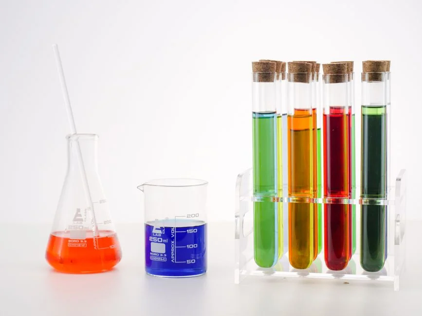
Cycles of concentration (CoC) is the ratio of total dissolved solids in the recirculating cooling water to the TDS of the makeup water, and it sets both freshwater consumption and blowdown quality. At 4 CoC, a typical data center loses 25-30% of its makeup to blowdown; at 6 CoC, blowdown drops to 15-20% but TDS climbs into the 4,000-6,000 mg/L range (Genesis Water Technologies, 2026). Pushing cycles higher reduces freshwater withdrawal but compresses the chemistry window: silica, calcium carbonate, and calcium sulfate all approach saturation at the same time, and the operator trades water savings for membrane scaling risk downstream.
For an Amsterdam blowdown stream the typical envelope is TDS 1,200-6,000 mg/L depending on CoC and source water, calcium 200-800 mg/L as CaCO3, magnesium 50-300 mg/L as CaCO3, silica 20-120 mg/L, alkalinity 100-400 mg/L as CaCO3, and 10-50 mg/L suspended solids, with accumulated biocides, corrosion inhibitors, and biofilm fragments riding on top. The binding constraint for RO recovery in the Randstad is silica: surface water in the western Netherlands often carries 5-15 mg/L silica, and that figure concentrates 4-8x in the cooling loop, which is why a standard BWRO stage at 75-80% recovery will foul on silica long before it fouls on calcium carbonate. Anticipating this, the design target for a 2026 Amsterdam train is 4-6 CoC at the tower, with a downstream high-recovery stage that strips silica, calcium, and sulfate as controlled solids rather than letting them plate the membrane.
Pretreatment Train: Softening, Ultrafiltration, and Antiscalant Dosing
The job of the pretreatment train is to hand the RO membranes a feed that does not foul, does not scale, and does not carry over biological material. The standard lineup for an Amsterdam blowdown reuse loop is a twin-tank industrial water softener rated 1-45 T/h dropping hardness to less than 1 mg/L as CaCO3 and stabilizing the Langelier Saturation Index slightly negative, followed by a PVDF hollow-fiber UF at 0.03-0.1 micron with automatic backwash and air scour. UF permeate should land at SDI below 3 and turbidity below 0.2 NTU; chemical cleaning every 1-3 months is typical for blowdown service (Genesis, 2026). Just ahead of the RO high-pressure pump, an automatic antiscalant dosing skid injects a phosphate-free, silica-compatible antiscalant; legacy chromate and high-phosphate programs are out because they fail the biocide and metals limits under IED 2010/75/EU and they will poison downstream IX resin if a polishing step is added later.
The chemistry of this stage matters more than the equipment list. With CoC in the 4-6 range, hardness in the blowdown can swing 200-800 mg/L as CaCO3 across a single week, so a single-tank softener is a false economy. Twin-tank configuration with 24-hour regeneration cycles keeps hardness on target through peak IT load, and the brine eluent from regeneration is captured for recycle into the high-recovery RO rather than trucked off site.
Reverse Osmosis for Blowdown Reuse: Conventional vs. High-Recovery Designs
Standard brackish water RO is the workhorse stage: 75-80% recovery, 150-400 psi operating pressure, 95-99% dissolved solids rejection, and 10-50 mg/L permeate TDS, with antiscalant holding calcium carbonate and calcium sulfate just below saturation. For an Amsterdam blowdown at 4 CoC and 2,500 mg/L TDS, a single BWRO pass produces about 1,875 mg/L of permeate-quality reuse water and 625 mg/L of concentrate at roughly 12,500 mg/L TDS, well above the local Hoogheemraadschap discharge cap of 1,500 mg/L without further treatment.
High-recovery designs close that gap. The architecture documented by IDE for cooling-tower blowdown combines RO with a fluidized bed reactor in which scaling inhibitors are intentionally deactivated, allowing silica, calcium carbonate, and calcium sulfate to precipitate onto seed material as compact pellets rather than plate the membrane. The decanted brine is then primarily NaCl and can be recirculated within the same loop, taking overall recovery to about 95% and permeate silica to roughly 1 mg/L. Dynamic RO cycling, alternating short production periods with high-velocity flushes, keeps the membrane surface inside the induction phase of crystallization and extends chemical cleaning intervals. A secondary IX polishing step is sometimes added to drop residual silica below 0.5 mg/L where the permeate feeds a chiller or adiabatic cooler with very tight chemistry. For procurement, the industrial RO system and the RO and UF membrane elements should be specified together so the element selection matches the recovery and flux targets.
| Parameter | Conventional BWRO | High-recovery RO (chemistry-managed) |
|---|---|---|
| Recovery | 75-80% | 90-95% overall |
| Operating pressure | 150-400 psi | 200-450 psi plus recycle pump |
| Permeate TDS | 10-50 mg/L | 5-20 mg/L |
| Permeate silica | 1-5 mg/L | ~1 mg/L (or <0.5 with IX polish) |
| Concentrate TDS | 8,000-15,000 mg/L | 20-30% dissolved solids as slurry |
| Chemical cleaning interval | 4-8 weeks | 12-20 weeks with dynamic cycling |
| Indicative capex (50,000 GPD) | $250,000-500,000 | $600,000-1,200,000 |
Brine and Concentrate Management: IX Regeneration, Partial ZLD, and Discharge Options
The 5-10% of feed flow that leaves the high-recovery loop is a small, highly concentrated stream, and the design choice is what to do with it. Ion-exchange spent regenerant is itself a brine stream loaded with hardness, and Brine Consulting documents the value of routing that regenerant back into the high-recovery RO loop rather than hauling it off site, which both cuts waste-handling cost and recovers a marginal additional volume of permeate. Where the remaining concentrate still exceeds the Hoogheemraadschap 1,500 mg/L TDS cap, mechanical vapor compression is the next step. MVC delivers 95-98% recovery on the concentrate, distillate below 10 mg/L TDS, and energy consumption of 15-25 kWh per 1,000 US gallons of distillate, with capital cost of $1-3 million for a 10,000-30,000 GPD unit (Genesis, 2026).
Full ZLD, meaning RO plus thermal evaporation plus a brine crystallizer producing a dry salt cake, achieves 95-99% overall recovery but carries $3-8 million of capex and $5-15 per thousand gallons of opex. For most Amsterdam sites that figure does not close, because the local waterboard does allow treated discharge at TDS below 1,500 mg/L and there is no abstraction ban. A partial ZLD at 80-90% volume reduction paired with permitted discharge of the residual stream is usually the defensible compromise, and the opex penalty versus full ZLD is significant without a corresponding permit benefit. The decision rule is straightforward: if the Hoogheemraadschap permit allows TDS below 1,500 mg/L, specify partial ZLD or direct permitted discharge; if it does not, escalate to full ZLD and document the capital case against a paid discharge alternative.
Recommended 2026 Treatment Train for an Amsterdam Data Center
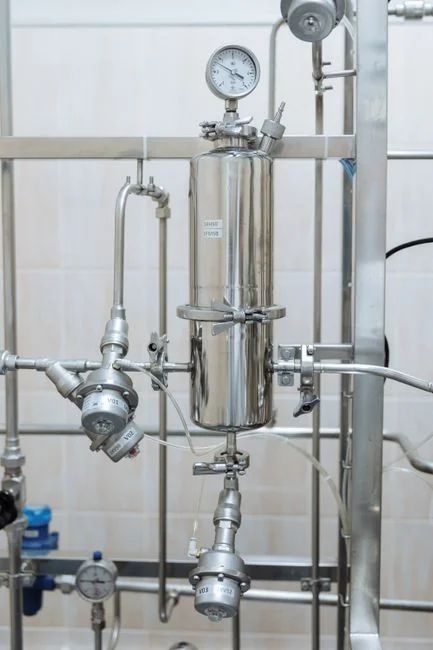
The defensible 2026 train for a 100 MW-class Amsterdam data center is sequenced as follows: canal or treated-effluent intake, screened and pH-adjusted; a high-efficiency sedimentation tank for coagulated turbidity and metal hydroxide removal; a multimedia filter at 10-15 micron; a twin-tank softener dropping hardness to less than 1 mg/L as CaCO3; a PVDF UF system at 0.03-0.1 micron with SDI below 3; phosphate-free antiscalant dosing; a primary BWRO at 75-80% recovery; a high-recovery RO stage with controlled precipitation in a fluidized bed reactor to strip silica, calcium, and sulfate; IX polish only if the permeate targets a chiller at very tight chemistry; recycle of IX regenerant into the high-recovery loop; and either partial ZLD via MVC or permitted discharge of the residual stream at TDS below 1,500 mg/L. Stormwater and site runoff can be segregated and treated through an MBR-integrated wastewater treatment line if the site plan includes a separate landscape or greywater reuse stream.
The mass balance at design CoC of 5 and high-recovery RO at 95% overall recovery lands at roughly 95% of total makeup returned as cooling reuse, 1-3% leaving the site as dewatered solids for landfill, and 2-4% as MVC distillate or permitted discharge at TDS below 1,500 mg/L. That envelope satisfies EU IED 2010/75/EU, EU WFD 2000/60/EC, and the local waterboard reuse targets in a single design, and it gives the operator a defensible number to file in the 2026 water-stress report.
| Stream | Volume share | Destination |
|---|---|---|
| Cooling tower permeate reuse | ~95% | Cooling tower makeup |
| Dewatered solids (silica, CaCO3, CaSO4 pellets) | 1-3% | Landfill or beneficial reuse |
| MVC distillate or permitted discharge | 2-4% | MVC distillate to cooling; discharge at TDS <1,500 mg/L |
2026 Dutch and EU Compliance Checklist
The 2026 permit envelope for an Amsterdam data center is built from four binding instruments. The EU Water Framework Directive 2000/60/EC sets the abstraction and discharge quality baseline for any surface or canal water source. The EU Industrial Emissions Directive 2010/75/EU governs cooling chemistry, biocide selection, and waste handling, and is the reason chromate and high-phosphate programs are no longer defensible. The EU Urban Waste Water Directive 91/271/EEC applies when treated WWTP effluent is part of the intake mix or when site wastewater is co-mingled with municipal streams. Finally, the local Hoogheemraadschap discharge permit sets site-specific limits on TDS (typically below 1,500 mg/L), heat load to surface water, nitrogen and phosphorus load, and biocide residuals.
Three practical triggers deserve specific attention. First, chromate and high-phosphate biocide residuals are effectively banned; specify non-phosphate, low-toxicity programs from day one. Second, surface-water discharge heat-load limits can dictate how much tower heat is rejected to air versus water, which feeds back into the cooling architecture. Third, the Netherlands is moving toward mandatory water-stress and reuse reporting for hyperscalers from 2026, so reuse percentage, freshwater offset, and blowdown volume per MWh should be tracked and audited from the first day of operation. The compliance map is not complicated, but it has to be assembled in the front-end design, not retrofitted after the waterboard issues a non-conformance.
Frequently Asked Questions
Is canal-water cooling safe for an Amsterdam data center?
Yes, provided the canal water is conditioned through coagulation, multimedia filtration, and 0.03-0.1 micron UF before it enters the cooling loop, and provided the cooling loop is a closed evaporative cycle with blowdown treated through RO before any discharge. Canal water at 8-18 °C actually lowers chiller lift, but it does carry 5-15 mg/L silica and biological load that must be controlled upstream.
How much blowdown does a typical 100 MW data center produce?
At 4 cycles of concentration, blowdown runs 25-30% of makeup water, which for a 2 million liter per day facility is 500,000-600,000 liters per day. At 6 cycles, blowdown drops to 15-20% of makeup, but TDS climbs into the 4,000-6,000 mg/L range and the chemistry window tightens significantly (Genesis, 2026).
What is the practical recovery limit for an RO system treating Amsterdam blowdown?
A standard BWRO stage on Randstad surface water is limited to 75-80% recovery by silica scaling at 4-8x concentration. A chemistry-managed high-recovery RO that strips silica, calcium, and sulfate as controlled solids in a fluidized bed reactor reaches about 95% overall recovery with permeate silica around 1 mg/L, which is the realistic ceiling for 2026 designs (IDE, 2026).
Does an Amsterdam data center need full ZLD?
Almost never. Full ZLD at $3-8 million of capex and 95-99% overall recovery is justified only where discharge is banned entirely. In the Randstad, the Hoogheemraadschap allows treated discharge at TDS below 1,500 mg/L, so a partial ZLD at 80-90% volume reduction or a permitted discharge of the RO residual is the standard 2026 answer.
What is the most common Dutch permit trigger for a new data center?
The Hoogheemraadschap discharge permit, specifically the TDS cap (below 1,500 mg/L), the biocide and metals limits under IED 2010/75/EU, and the surface-water heat-load limit. Reuse percentage and freshwater offset reporting become mandatory for hyperscalers from 2026, so the design must meter and log those numbers from the first day of operation. For multi-region fleet operators, the engineering logic is portable; the data center blowdown treatment in Mombasa and the Astana data center blowdown guide cover the same train under different intake and discharge envelopes, and the broader RO vs ion exchange OPEX comparison is useful when sizing the IX polish step.