Why Nagoya Data Centers Need a Dedicated Blowdown Treatment Train in 2026
A 100 MW hyperscale data center consumes up to 2 million liters of water per day (source: IDE-tech, 2026), and Nagoya's Minato-ku and Nakamura-ku waterfront industrial zones are now in the permitting pipeline for facilities of that scale, driven by METI's semiconductor and digital-infrastructure investment program. The Kiso River system that supplies the city's municipal and industrial users is under formal review: Aichi Prefecture flagged industrial freshwater competition as a 2025-2026 planning item, and a new build drawing 1-2 ML/day is no longer treated as a routine connection by Nagoya City Waterworks Bureau. Conventional facilities purge 20-40% of intake as cooling-tower blowdown (source: Genesis Water, 2026); for a 10 MW site running at 4 cycles of concentration that is roughly 3.75 million gallons per month of water already paid for, already conditioned, and currently going to drain. Treating that stream as waste is a position the Aichi permitting authority will no longer accept without a water-stewardship plan, mirroring the METI/AICHI guidance that now references global hyperscaler benchmarks such as Google's 120% replenishment pledge (source: Ketos, 2026). The rest of this article works through the local water chemistry, the equipment train an EPC can transcribe into a P&ID, the reference parameters for a 50 MW hall, the Japanese compliance stack, and the cost math a finance committee will ask for.
Cooling Tower Blowdown Chemistry: What Makes Nagoya Water Different
Cooling-tower blowdown (CTBD) is the purge stream operators discharge to keep dissolved solids from concentrating past the cooling system's scaling and corrosion limits. The blowdown ratio is 1 / (CoC − 1): at 4 cycles of concentration the blowdown equals 25% of makeup water, and at 6 CoC it drops to 20% (source: Genesis Water, 2026). The stream itself is enriched in silica, calcium carbonate, calcium sulfate, and chloride, plus residual treatment chemicals — phosphonates, biodispersants, biocides — added upstream to keep the loop clean. Nagoya's municipal water is Kiso-derived and moderately soft, with total hardness typically 40-60 mg/L as CaCO₃, but it carries seasonal silica that, combined with the city's humid subtropical summer, promotes biological fouling and pushes conventional RO scaling limits tighter than the U.S. Southwest case studies the equipment vendors usually reference. Conventional brackish-water RO plateaus at 75-80% recovery before silica and CaSO₄ scaling become unmanageable (source: IDE-tech, 2026); pushing beyond that requires chemistry management rather than just higher feed pressure. The other framing point that often gets lost: roughly 70-80% of evaporative cooling water leaves as vapor, leaving 20-30% as the recoverable blowdown stream (source: Ketos, 2026). That 20-30% is the engineering target for any reuse train, and a multi-media filter for RO pretreatment is the standard first polishing step before the membranes see that stream.
The 2026 Treatment Train: From Bar Screen to Polished Reuse Water
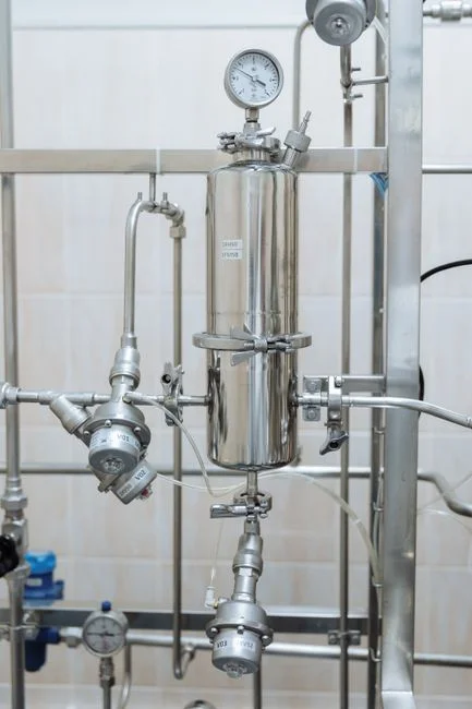
The train below is the configuration an EPC should drop into a P&ID for a Nagoya evaporatively cooled hall. Each stage has a defined influent/effluent target so the contractor can size the unit operation, not the vendor.
- Stage 1 — Rotary mechanical bar screen. A rotary mechanical bar screen with 3-10 mm bar spacing removes rags, plastics, and debris from the basin-side blowdown collection sump and protects downstream pumps and membranes from mechanical damage.
- Stage 2 — Dissolved air flotation. A DAF system for suspended solids and biological load strips FOG, total suspended solids, and microbial floc before the RO feed; this stage is non-negotiable in Nagoya's humid summer when biological load spikes.
- Stage 3 — Multi-media filtration. Reduces the silt density index to SDI < 5, the standard RO pretreatment target, by capturing the particulates DAF cannot lift.
- Stage 4 — Ultrafiltration. A PVDF ultrafiltration system rated 2,000-40,000 L/h at 0.03 µm removes colloids, bacteria, and residual turbidity up to 300 ppm; automatic backwash plus air scour keeps chemical consumption low.
- Stage 5 — High-recovery reverse osmosis. The core of the train. A high-recovery industrial RO system operated at up to 95% recovery produces a permeate with SiO₂ around 1 mg/L (per the IDE-tech MAXH₂O case study), versus the 75-80% ceiling of a conventional BWRO skid.
- Stage 6 — Polishing and disinfection. A chemical-free UV polishing step handles loop-side biological control with no residual; where a residual is required for the cooling loop, an on-site ClO₂ generator is the alternative.
- Optional Stage 7 — Side-stream chemical dosing. A PLC-controlled chemical dosing skid for anti-scalant and biodispersant on the RO feed is what allows cycles of concentration to climb past 6 without membrane fouling.
| Stage | Unit Operation | Influent Target | Effluent Target | Design Note |
|---|---|---|---|---|
| 1 | Rotary bar screen | Raw CTBD from basin | Debris-free liquid | 3-10 mm bar spacing |
| 2 | DAF | TSS up to ~500 mg/L | TSS < 30 mg/L | Critical in Nagoya humid season |
| 3 | Multi-media filter | SDI 5-10 | SDI < 5 | RO feed protection |
| 4 | UF (PVDF, 0.03 µm) | Turbidity < 5 NTU | SDI < 3, turbidity < 0.5 NTU | Auto backwash + air scour |
| 5 | High-recovery RO | Free Cl₂ < 0.1 mg/L | TDS < 50 mg/L, SiO₂ ≤ 1 mg/L | Up to 95% recovery |
| 6 | UV or ClO₂ | RO permeate | Biologically stable | UV no residual; ClO₂ residual |
| 7 | Anti-scalant / biodispersant dosing | RO feed | Stable at CoC 6+ | PLC-controlled metering |
Reference Parameter Table for a 50 MW Nagoya Hyperscale Hall
These numbers scale linearly from the 2 ML/day-at-100 MW reference (source: IDE-tech, 2026) and are sized for a 50 MW evaporatively cooled hall on the Nagoya waterfront. They are the values an engineer should put in front of a Japanese general contractor at the basic-design stage.
| Parameter | Value | Source / Note |
|---|---|---|
| IT load | 50 MW | Reference hyperscale hall |
| Freshwater intake | 1.0-1.2 ML/day | Proportional to IDE-tech 100 MW figure |
| CTBD flow at 4 CoC | 280-300 kL/day | 25% of makeup per Genesis Water ratio |
| RO feed (after UF) | SDI < 3, turbidity < 0.5 NTU, free Cl₂ < 0.1 mg/L | Standard RO feed spec |
| RO permeate | TDS < 50 mg/L, SiO₂ ≤ 1 mg/L, conductivity < 100 µS/cm | Meets JIS B 0034 cooling-tower makeup guidelines |
| RO concentrate | ~95% volume reduction vs. feed | Routed to brine stage |
| Concentrate dewatering | Plate-and-frame filter press | Solid waste to approved handler |
| Polished reuse water | Blended with freshwater for makeup | Net freshwater draw reduction ~80-85% |
| Side-stream dosing | PLC-controlled anti-scalant skid | Allows CoC > 6 |
Japanese Compliance: Water Pollution Control Act, Sewerage Law, and Aichi Ordinances
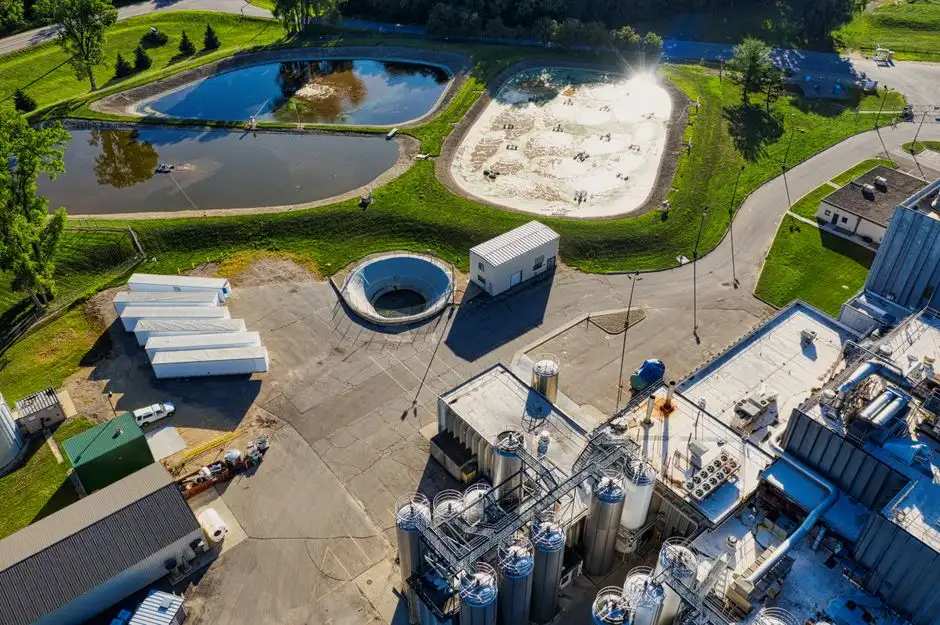
The compliance stack a Nagoya data center must clear is layered, and the on-site reuse train is what makes the math work. The Water Pollution Control Act (水質汚濁防止法) sets the national effluent envelope: pH 5.0-9.0 (sea-zone discharges also 5.0-9.0), COD ≤ 160 mg/L on a 3-hour daytime average, and SS ≤ 200 mg/L maximum with a 100 mg/L daily average for discharges to public water bodies. Sending >85% of blowdown back to the cooling loop as polished reuse, and routing the small polishing-reject stream to the public sewer, is the configuration that holds the site inside the envelope. The Sewerage Law (下水道法) Article 12, enforced through Nagoya City's sewer-acceptance ordinance, sets tighter limits on SS, BOD, and n-hexane extracts than the national act; the Aichi Prefecture ordinance layers on site-specific items, including total phosphorus and total nitrogen caps if the site falls inside a designated lake or waterbody protection zone. The analytical suite the on-site or contract lab must run to demonstrate compliance sits inside JIS B 0034, JIS K 0101, and JIS K 0102 — pH, SS, COD, T-N, T-P, n-hexane extracts, and trace metals at the JIS-specified detection limits. Zero liquid discharge is rarely required in Nagoya's climate; high-recovery RO plus sewer discharge of the polishing reject is the standard 2026 compliant path.
| Parameter | Water Pollution Control Act (national) | Sewerage Law / Nagoya ordinance | 2026 reuse-train implication |
|---|---|---|---|
| pH | 5.0-9.0 (sea: 5.0-9.0) | 5.0-9.0 typical | RO permeate within range |
| COD | ≤ 160 mg/L (3-h avg, daytime) | Tighter by ordinance | Reject to sewer, not river |
| SS | ≤ 200 mg/L max, 100 mg/L daily avg | Tighter by ordinance | DAF + MMF keep SS well below |
| T-N, T-P | Site-specific in protected zones | Aichi ordinance caps apply | Bias toward sewer discharge |
| n-hexane extracts | Mineral oil ≤ 5 mg/L typical | Tighter by ordinance | DAF removes FOG |
Cost, ROI, and Right-Sizing the System for a Colocation vs. Hyperscale Build
Hyperscale RO economics do not translate 1:1 to a 5 MW colocation hall. Per-gallon CAPEX at smaller facilities runs 3-4× higher than at hyperscale (source: Genesis Water, 2026), and the operation typically cannot staff dedicated membrane operators. The practical 2026 answer for a mid-size Nagoya build is a modular skid in the 100-300 GPM range, sized to blowdown flow rather than total facility flow. As a reference framing — illustrative, not a quotation — a 15 MW water-stressed site spending roughly $200,000 of CAPEX to recover 60% of blowdown shows about a 6.7-year simple payback on water alone; once avoided discharge fees, freshwater connection charges, and chemical savings are layered in, payback compresses to 3-5 years (source: Genesis Water, 2026). OPEX in Japan is dominated by industrial electricity at ¥17-25/kWh, membrane replacement on a 3-5 year cycle (a stocked RO and UF membrane filter element inventory cuts swap downtime), UV lamp or ClO₂ service, and consumables fed by the PLC-controlled chemical dosing skid. The hidden savings are the line items the finance committee often misses: reduced freshwater connection fees paid to Nagoya City Waterworks Bureau, lower discharge-volume sewerage fees, and eligibility for METI/AICHI water-efficiency subsidies once the reuse percentage is documented. That documented percentage is also what feeds the ESG reporting cycle — TCFD and CDP Water Security disclosures are now standard asks from Japanese institutional investors. For facilities that need replacement wear parts during the build, a stocked parts and media inventory keeps the commissioning schedule from slipping.
Frequently Asked Questions
What is the typical recovery rate for cooling tower blowdown RO in Japan?
A conventional brackish-water RO skid plateaus at 75-80% recovery on Nagoya CTBD before silica and CaSO₄ scaling become unmanageable (source: IDE-tech, 2026). High-recovery designs that combine chemistry management and dynamic RO operation reach approximately 95% recovery, with permeate silica around 1 mg/L — suitable for reuse as cooling-tower makeup.
Does a Nagoya data center need a permit to discharge blowdown to the public sewer?
Yes. Discharge to the Nagoya municipal sewer requires compliance with Sewerage Law Article 12 thresholds, which the city enforces through its own ordinance and which are typically tighter than the national Water Pollution Control Act envelope. A pre-treatment permit and an effluent-monitoring plan are required before commissioning.
Can a small 5 MW colocation site justify a high-recovery RO skid?
Not by copying hyperscale economics — per-gallon CAPEX runs 3-4× higher at smaller scale (source: Genesis Water, 2026). The right answer is a modular 100-300 GPM skid sized to blowdown flow only, with payback typically 3-5 years once avoided freshwater, discharge, and chemical costs are accounted.
What influent parameters most often cause RO fouling in Japanese data centers?
Silica and calcium sulfate scaling above 75-80% recovery, plus biological fouling driven by the humid subtropical summer. DAF upstream of UF, SDI < 3 at the RO feed, free chlorine < 0.1 mg/L, and a PLC-controlled anti-scalant dosing program are the standard countermeasures.
Is zero liquid discharge (ZLD) required for data centers in Aichi Prefecture?
No. ZLD is rarely required in Nagoya's climate under current Aichi ordinances. The 2026 compliant path is high-recovery RO returning permeate to the cooling loop, with the small polishing-reject stream discharged to the public sewer under Sewerage Law Article 12. A facility considering an MBR integrated wastewater treatment train would do so for water-quality reasons, not regulatory mandate.