
Why Suppesville Petroleum Plants Are Rethinking Primary Treatment in 2026
U.S. EPA 40 CFR Part 419 refinery effluent limits, combined with NPDES oil and grease benchmarks sitting at 10–15 mg/L in most Suppesville discharge permits, are forcing refiners, tank farms, and lube-oil blenders to replace under-sized legacy equipment in 2026 (per EPA 40 CFR Part 419). At the same time, Suppesville's industrial corridor is under water-reuse pressure from the municipal supplier, which makes a single-pass clarifier that sends 50–70% of its TSS to the river a non-starter for plants chasing recycle.
The typical Suppesville petroleum waste stream is not a textbook sample. Tank-farm drainage delivers slugs of free oil after heavy rain. Desalter brine carries emulsified FOG stabilized by surfactants. Corrosion scale, sand, and catalyst fines push TSS to 1,000–2,000 ppm. Temperatures swing from 25 °C in stormwater sumps to 60–70 °C at desalter overflow, which changes oil viscosity and emulsion stability inside the separator. Truck offloading at the terminal adds another slug load every shift. A rectangular clarifier built in the 1990s cannot hold a consistent overflow rate against that variability.
This is why the practical question in 2026 is not "clarifier or DAF" in the abstract — it is which unit sits between the API separator and the biological or reuse step, and whether the existing clarifier is the bottleneck or a free-oil knockout is the missing piece. Older Suppesville plants retrofitting legacy API separators and rectangular clarifiers are the ones driving the current DAF upgrade wave.
DAF vs Clarifier at a Glance: How They Actually Differ
DAF lifts contaminants to the surface on 20–50 µm micro-bubbles; a clarifier lets heavy solids settle by gravity. That single mechanical difference is why DAF removes 85–98% TSS on petroleum streams while a conventional clarifier typically achieves 50–70% (per DAF Corp FC Maximizer data, 2025-08) and 85–90% on RC UniMax rectangular units (per DAF Corp, 2025-08). For Suppesville streams dominated by free oil, emulsified FOG, and low-density TSS, flotation wins on the contaminant that matters most.
| Parameter | Dissolved Air Flotation (DAF) | Conventional Gravity Clarifier |
|---|---|---|
| Separation driver | 20–50 µm micro-bubbles attach to oil/floc and float it (per Clearwater S1; DAF Corp micro-bubble generator) | Gravity settling of heavy solids only |
| Target contaminant | Free oil, emulsified FOG, low-density TSS, light grit | Heavy settleable solids (sand, scale, grit) |
| TSS removal efficiency | 85–98% (per DAF Corp FC Maximizer, 2025-08) | ~50–70% typical on refinery streams |
| Example performance | FC-150: 2,000 ppm → 50 ppm at 500 gpm; total to <20 ppm filterable (per DAF Corp S2) | 1,000 ppm → 300–500 ppm typical |
| Footprint | Compact skid; ≤66 gpm single skid, modular two-skid above (per Clearwater S1) | Large concrete basin, high area per m³/h |
| Sludge consistency | 2–4% DS float (per DAF Corp S2); thicker, easier to dewater | 1–2% DS underflow; thin, voluminous |
| Chemical demand | pH adjustment + coagulant + polymer flocculant, jar-tested per stream | Often none for primary settling; polymer only for sludge thickening |
| Oil and grease removal | High; handles emulsified FOG via chemistry + bubble attachment | Poor on emulsified oil; only free oil that rises naturally |
| Capacity range | 10–11,000 gpm (per DAF Corp FC Maximizer); 10–1,000 gpm RC UniMax | Set by basin area; large plants need very large footprints |
| Best fit at Suppesville | Primary clarifier after API/CPI knockout, ahead of bio or reuse | Stormwater settling, sludge thickener, post-bio polishing |
The mechanical story explains the table: a clarifier is a sedimentation device, so it cannot lift emulsified oil. DAF pressurizes clarified water with air at roughly 100 psi (per Aries S5), then releases it through a nozzle to nucleate micro-bubbles that nucleate onto floc and oil droplets. At Suppesville scale, capacity is not the constraint — DAF Corp's FC Maximizer covers 10–11,000 gpm and the rectangular RC UniMax covers 10–1,000 gpm (per DAF Corp S2).
How a DAF System Treats Petroleum Wastewater Step by Step
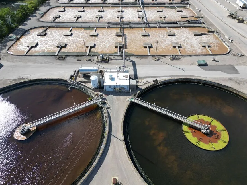
A DAF treats petroleum wastewater in seven linked stages: screening, equalization, chemical conditioning, flocculation, pressurization, flotation, and skimming. The pressurization step is what makes DAF different from a clarifier — clarified water is recycled, saturated with air at ~100 psi in an air-mixing tube, then released into the float tank where 20–50 µm micro-bubbles nucleate and attach to oil droplets and floc (per Aries S5; DAF Corp micro-bubble generator).
- Influent screening and equalization: remove rags and large debris; dampen slug loads from truck offloading or tank-farm drainage so the chemistry sees a steady matrix.
- Chemical conditioning: inject pH adjustment (acid or caustic), then coagulant for charge neutralization on emulsified oil droplets. A coagulant is fed into the influent pipe; pH control and flocculant are added downstream in the flocculation section (per Aries S5).
- Flocculation: a long-chain polymer is added in flocculation tubes (15–45 second flash mix, per Clearwater S1) or in mix tanks with impeller agitators for longer contact time. Jar testing determines the program — it is not optional for any Suppesville refiner.
- Pressurization: clarified effluent is recycled through a recirculation pump and saturated with air at ~100 psi in an air-mixing tube (per Aries S5; DAF Corp S2). The system must start on clean water; filling a DAF with raw oily wastewater on day one damages the recirculation pump and air saturation system (per Clearwater S1).
- Flotation: the saturated recycle stream is released into the float tank through a pressure-reduction nozzle. Micro-bubbles 20–50 µm form, attach to oil and floc, and lift the float to the surface as a sludge blanket.
- Skimming: a chain-and-flight or rotary scoop mechanism drags the float over a beach plate into a sludge sump. 304SS flights with chemical- and heat-resistant wipers are standard (per Aries S5).
- Clarified water draw-off: treated water is recovered from below the sludge blanket and above the settled-solids zone, ready for biological treatment, media filtration, or reuse.
Plate packs in designs like the Clearwater FPBC and Pan America PDHR/PDHF increase overflow rate per unit area by adding laminar-flow inclined plates above the bubble zone — a useful upgrade for Suppesville plants that need more capacity inside an existing footprint (per Clearwater S1; Pan America S4). A circular zero-velocity DAF such as the HydropureWater DAF system targets the 92–98% TSS removal band that refinery NPDES permits demand.
When a Conventional Clarifier Still Makes Sense in a Suppesville Refinery
A conventional or lamella clarifier earns its place on a Suppesville site in three scenarios: heavy settleable solids with little free or emulsified oil, large available footprint with a tight CAPEX ceiling, or as a polishing step downstream of biological treatment. A plain rectangular clarifier cannot break an oil emulsion, so a Suppesville plant that relies on it as the only oil-removal step will fail NPDES O&G limits — that is the failure mode worth flagging in any project meeting.
The modern upgrade to a legacy rectangular clarifier is a lamella or inclined-plate clarifier. Surface loading rates of 20–40 m/h are typical, with up to 30% lower chemical consumption versus conventional basins because the inclined plates shorten the settling path and thicken the underflow. On Suppesville sites, a HydropureWater lamella clarifier fits as a post-DAF polisher for residual TSS, or as a primary settler on inorganic-laden refinery streams (stormwater, once-through cooling side-stream solids, boiler blowdown).
The practical Suppesville pattern is therefore not "DAF or clarifier" — it is "API/CPI knockout → DAF as primary clarifier/separator → optional lamella polish." A plain clarifier is still the right tool for sludge thickeners, equalization surge, and stormwater settling where oil is not the limiting contaminant.
Refinery-Scale Sizing and Skid Options for Suppesville Plants
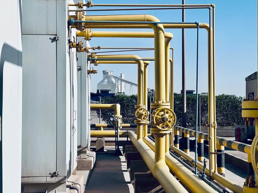
Suppesville flow rates fall into a small number of repeatable DAF architectures, so procurement can map a gpm figure to a vendor model before the RFQ goes out. Below 66 gpm, a single-skid COMPACT DAF covers the duty with chemical conditioning, sensors, and a PLC control panel integrated (per Clearwater S1). From 48 to 450 gpm, the skid-mounted FC Maximizer line spans 6 ft to 15 ft diameter tanks and arrives preassembled with piping, valves, and controls wired (per DAF Corp S2). At 500 gpm, the FC-150 example clarifies 2,000 ppm TSS down to 50 ppm — a useful benchmark for a Suppesville refinery or lube-oil blender (per DAF Corp S2).
| Suppesville flow band | Recommended DAF architecture | Typical footprint |
|---|---|---|
| ≤66 gpm (≤15 m³/h) | Single-skid COMPACT DAF with integrated chemical conditioning (per Clearwater S1) | One shipping skid, plug-and-play |
| 48–450 gpm (11–102 m³/h) | Skid-mounted FC Maximizer, 6–15 ft diameter, 304L stainless (per DAF Corp S2) | Skid plus small chemical skid; HydropureWater automatic chemical dosing system sized to match |
| 100–500 gpm (23–114 m³/h) | Modular two-skid DAF, or rectangular RC UniMax (per DAF Corp S2; Clearwater S1) | Two skids side by side, common chem panel |
| 4–300 m³/h mid-band refinery/terminal | HydropureWater DAF, 13 standard models, petrochemical-proven | Compact skid, epoxy-coated carbon steel or 304L/316 SS |
| 1,000+ gpm (227+ m³/h) | Rectangular RC UniMax or cross-flow/counter-current FPHF (per DAF Corp S2; Clearwater S1) | Rectangular basin, larger skimmer geometry |
Two sizing caveats matter for Suppesville. First, the chemical program is part of the DAF scope, not an accessory — an undersized coagulant or polymer feed will cap TSS removal at 70% regardless of the float tank. Second, very large units (above 1,000 gpm) tend toward rectangular cross-flow or counter-current geometries because the skimmer surface area on a circular tank becomes a hydraulic bottleneck; the FPHF combines cross-flow and counter-current flow for that duty (per Clearwater S1).
2026 Cost and Footprint Snapshot for Suppesville Buyers
Procurement at Suppesville refineries needs order-of-magnitude CAPEX bands per m³/h, not vendor list prices, because material of construction is the dominant cost driver. The DAF Corp standard FC Maximizer ships as all 304L stainless with epoxy-painted carbon-steel tank bottom supports; full stainless is available on request (per DAF Corp S2). A Suppesville plant buying on that baseline can expect a 20–40% CAPEX premium for full 316L stainless driven by chloride-rich desalter brine or high-temperature service.
Footprint is where DAF pulls away from a clarifier. A single COMPACT DAF handles ≤66 gpm on one shipping skid (per Clearwater S1); a conventional clarifier delivering the same hydraulic loading needs a concrete basin measured in tens of square meters. Sludge handling closes the loop: DAF float at 2–4% dry solids (per DAF Corp S2) cuts downstream dewatering load versus a clarifier's 1–2% underflow, and the standard downstream step is a HydropureWater plate and frame filter press to bring the float to a handleable cake for off-site disposal or sludge-to-soil blending.
For 2026 budgeting, treat CAPEX as low-six-figures USD per 10 m³/h for a packaged skid DAF in epoxy-coated carbon steel, scaling into seven figures only at the largest rectangular basins above 200 m³/h with full stainless construction. OPEX sensitivity is dominated by polymer consumption (kg per m³ treated) and sludge hauling cost per ton of dry solids — both of which DAF's thicker float helps reduce.
Decision Framework: DAF, Clarifier, or Both for Your Suppesville Plant
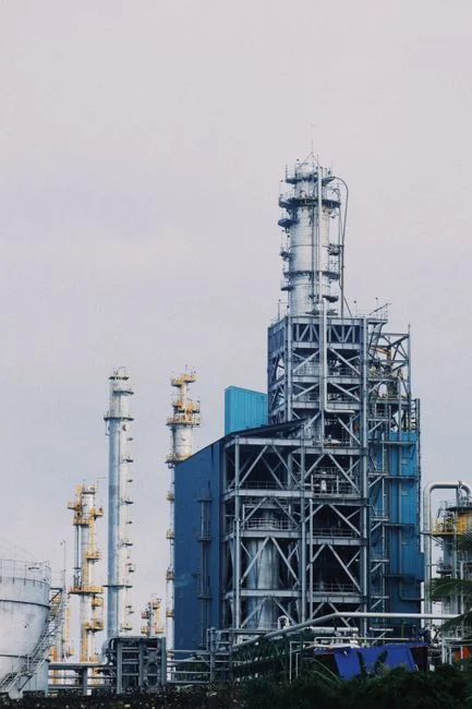
The cleanest go/no-go for a Suppesville project meeting is a stream-profile matrix. The default rule for petroleum service in 2026 is API/CPI knockout first, then a DAF as the primary clarifier/separator, with a lamella polish only if downstream TSS is the bottleneck. A standalone clarifier is the right call only for streams with no free or emulsified oil.
| Stream profile at Suppesville | Recommended primary unit | Polish step (if any) |
|---|---|---|
| Free oil + emulsified FOG + TSS (desalter brine, tank-farm drainage, lube-oil blender washwater) | API/CPI separator → DAF (e.g., HydropureWater DAF or DAF Corp FC Maximizer) | Optional lamella or multimedia filter before reuse |
| High emulsified FOG, little settleable solids (refinery process condensate, surfactant-laden washwater) | DAF as primary; no API needed if free oil is low | Biological treatment (MMBBR or activated sludge) for COD/BOD |
| Stormwater runoff, high settleable solids, little oil | Conventional or lamella clarifier | Oil-water separator downstream if sheen detected |
| Sand, scale, grit from cooling-water side-stream | Lamella clarifier (e.g., HydropureWater high-efficiency sedimentation tank) | None typically; send sludge to thickener |
| Post-biological effluent polishing for TSS | Lamella clarifier or DAF (low-load) | Media filtration or membrane ahead of reuse |
Two process steps should sit ahead of any equipment decision. First, jar testing on real Suppesville wastewater — Aries, DAF Corp, and most vendors offer this — to confirm coagulant and polymer selection. Second, on-site pilot feasibility at 50–100 gpm; DAF Corp explicitly offers pilot FC-60 and RC UniMax pilots at 48–200 gpm for exactly this purpose (per DAF Corp S2). A pilot is the cheapest insurance against buying a DAF chemistry program that does not work on a Suppesville emulsion.
Frequently Asked Questions
Is DAF enough on its own for refinery wastewater, or do I need an API separator first?
For Suppesville refineries, an upstream API or corrugated-plate interceptor (CPI) is best practice. The API/CPI removes free oil before the DAF, which protects the saturation system from fouling, reduces chemical load, and prevents the float tank from seeing a slug of free oil that would otherwise capitate the bubble blanket. DAF Corp and Clearwater both design their systems to sit downstream of a primary oil-water separator.
What oil and grease removal can I expect from a DAF in petroleum service?
DAF typically removes 85–98% of TSS and the bulk of emulsified FOG on refinery streams, with effluent TSS commonly 10–50 ppm. DAF Corp's FC-150 example clarified 2,000 ppm influent TSS to 50 ppm at 500 gpm, with total filterable solids to below 20 ppm (per DAF Corp S2). Actual oil and grease removal depends on the emulsion stability and the chemistry program selected by jar testing.
How much floor space does a DAF need compared to a clarifier?
A DAF is a compact skid, while a clarifier needs a large concrete basin. Practical Suppesville thresholds are ≤66 gpm on a single skid (per Clearwater S1) and 48–450 gpm on skid-mounted FC Maximizer units from 6 ft to 15 ft diameter (per DAF Corp S2). For most Suppesville plant sizes, a DAF fits inside a standard equipment pad; the equivalent clarifier would need a much larger civil footprint.
Can a DAF handle the hot, oily wastewater from a Suppesville refinery or terminal?
Yes, with material-of-construction selection. DAF Corp's standard FC Maximizer is all 304L stainless with epoxy-painted carbon-steel supports, and full stainless is available on request (per DAF Corp S2). Aries constructs DAF clarifiers in epoxy-coated mild steel, stainless steel, or polyethylene depending on temperature and chemistry (per Aries S5). Pair the material choice with proper chemical conditioning for emulsion breaking.
What chemicals does a petroleum DAF need?
A refinery DAF needs three classes of chemicals: pH adjustment (acid or caustic to the optimum for flocculation), coagulant for charge neutralization on emulsified oil droplets, and a long-chain polymer flocculant to build floc. Mixing is done in flocculation tubes (15–45 second flash mix, per Clearwater S1) or in mix tanks with impeller agitators for longer contact time. Jar testing selects the program — it is not optional for a Suppesville refiner chasing NPDES O&G limits. A correctly sized HydropureWater automatic chemical dosing system ties the program to flow and TSS load.