Why Carol Stream Chemical Plants Are Re-evaluating Primary Clarification in 2026
For chemical plants in Carol Stream, IL in 2026, choose a DAF system when the wastewater contains emulsified oils, surfactants, or light suspended solids and you need >90% FOG removal in a compact footprint; choose a lamella clarifier when the stream is dominated by heavy settleable solids, metals-bearing precipitates, or grit and capital cost is the deciding factor. Most batch chemical reactors benefit from DAF as the primary stage, often paired with a clarifier for polishing.
Carol Stream's industrial corridor in DuPage County runs on batch chemistry: surfactants, paint and coatings, adhesives, sealants, and contract blending that ships in 50 to 5,000 gallon campaigns. That operating pattern produces a wastewater signature that defeats single-technology assumptions — flows swing from 30 to 110 m³/h between reactors dumping solvent washes, pH excursions hit 2 then 11 inside the same shift, and Total Toxic Organics (TTO) compliance under 40 CFR Part 414 has to be met every day, not averaged across a month.
Three regulatory frameworks govern a DuPage County chemical plant's discharge envelope: 40 CFR Part 414 (Organic Chemicals, Plastics, and Synthetic Fibers) sets the daily-maximum and monthly-average limits for BOD, TSS, and TTO; 40 CFR Part 433 (Metal Finishing) applies wherever a plating-adjacent line, catalyst prep, or pigment dispersion is present; and Illinois 35 IAC Part 309 establishes the receiving POTW's effluent standards that the DuPage County plant must meet before sewer discharge. Tightening daily-maximum limits on oil & grease, TSS, and metals (per 2026 Illinois EPA discharge guidance updates) make the primary clarifier choice a compliance decision, not just an OPEX decision.
Mechanistically, the choice sits on a single physical contrast: dissolved air flotation (DAF) uses buoyancy-driven attachment of 10–100 µm bubbles to lift low-density contaminants to the surface, while a lamella clarifier (inclined plate settler) uses gravity sedimentation at surface loadings of 20–40 m/h to settle heavier flocs down a stack of plates inclined at 55–60°. Match the dominant contaminant to the dominant force, and the rest of the design follows.
How Each Technology Actually Works in a Chemical Wastewater Stream
DAF performance is set by three numbers. The saturator runs at 4–6 bar to dissolve air into 20–40% recycle flow, achieving dissolved air concentrations of 70–100 mg/L. When that recycle stream passes through the pressure-reduction valve, the supersaturated air comes out of solution as a cloud of 10–100 µm microbubbles. The air-to-solids (A/S) ratio — typically 0.005–0.06 mL of air per mg of solids — governs attachment efficiency: too little air and removal collapses, too much and the blanket turns turbulent. Hydrophobic oil droplets attach to bubbles naturally; hydrophilic particles need coagulant (ferric chloride, polyaluminum chloride) and flocculant (cationic or anionic polymer) pre-conditioning to reverse surface charge and aggregate (per commercial DAF reference, 2026-08). Bubble-particle aggregates rise at 5–15 m/h and form a floating sludge blanket scraped by an automatic skimmer; clarified underflow exits from a submerged header. For a parallel deep-dive on bubble dynamics, saturator design, and A/S ratio tuning, see the engineering deep-dive on DAF mechanisms and A/S ratio design.
A lamella clarifier stacks inclined plates at 55–60° inside a fraction of the footprint of a conventional rectangular basin. Solids settle on the plate underside, slide down into a sludge hopper, and clarified water flows upward to a collection launder. Surface loading on a lamella clarifier runs 20–40 m/h, and sludge recirculation improves floc density while cutting polymer demand by up to 30% (HydropureWater catalog data, 2026). The hydrodynamic advantage is the shortened settling distance: particles only have to fall roughly 50–80 mm before hitting a plate, not 2–3 m as in a conventional clarifier. For heavy, dense solids — metal hydroxides, pigment fillers, catalyst fines — lamella wins on simplicity: no compressor, no saturator, no A/S ratio to maintain, lower operator skill required.
The recycle-press versus full-flow-press choice matters for shear-sensitive flocs. A recycle-press DAF (10–50% recycle pressurized) keeps coagulated flocs out of the saturator and protects fragile polymer bridges; a full-flow-press DAF saturates the entire stream and is used only when the chemistry is robust enough to survive the shear. Most Carol Stream batch chemical reactors use recycle-press for that reason.
DAF vs Clarifier: Side-by-Side Parameters for Chemical Plants
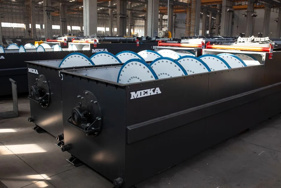
The table below is the working spec sheet a procurement manager can hand to a vendor and an engineer can hand to a regulator. Numbers are drawn from commercial DAF/clarifier case studies and HydropureWater field data, 2026.
| Parameter | DAF system | Lamella clarifier |
|---|---|---|
| Removal mechanism | Buoyancy — microbubble attachment lifts low-density particles to the surface | Gravity — inclined plates shorten settling distance for denser flocs |
| Best for | Emulsified oils, surfactants, FOG, latex, plasticizers, light TSS | Metal hydroxide sludges, pigment/filler, grit, high-density TSS |
| Hydraulic loading | 5–30 m³/m²·h (up to 40–50 with integrated plate packs) | 20–40 m/h surface loading on plate area |
| Typical removal efficiency | >90–95% FOG; 40–60% BOD reduction pre-biological (2026-08 DAF reference) | 70–90% TSS on heavy-solids streams; 70% FOG on the same stream (commercial case study, 2026) |
| Sludge dryness | 2–6% solids — reduces dewatering cost | 1–3% solids — higher dewatering volume |
| Footprint for 100 m³/h | ~3–6 m² at 20 m³/m²·h | ~2.5–5 m² at 25 m/h plate loading |
| Energy demand | Recycle pump + air compressor dominate; higher than clarifier | Sludge rake + polymer pump; modest |
| Chemical demand | Coagulant + flocculant common; A/S ratio critical | Polymer for flocculation; sludge recirculation cuts dose ~30% |
| CAPEX | Higher (compressor, saturator, skimmer) | Lower (no compressor, simpler controls) |
| OPEX | Energy + air; higher on a $/m³ basis | Polymer + rake torque; lower $/m³ for heavy solids |
| Operator skill | Higher — A/S ratio, saturator, jar testing | Lower — straightforward flow and sludge control |
For a 100 m³/h peak flow, a DAF at 20 m³/m²·h needs roughly 5 m² of flotation area; a lamella clarifier at 25 m/h needs about 4 m² of plate area. The footprint edge is smaller than the marketing literature suggests — the real discriminator is influent character, not square meters. For a benchmark against a different industry's effluent signature, see the DAF vs clarifier comparison for petroleum and oil-laden streams in the 2026 Kansas City guide.
When a DAF System Is the Right Choice in Carol Stream
DAF is the correct primary stage when the dominant contaminant is lighter than water, when the stream is emulsified, and when the plant needs rapid recovery from batch dumps. Trigger influent characteristics: emulsified oils and surfactants at 50–5,000 mg/L (per commercial DAF reference, 2026-08), solvents, plasticizers, latex and adhesive residues, FOG loadings tied to coating-line washouts, and any stream with sub-100 µm colloidal solids that won't settle by gravity. Trigger operating conditions: indoor or covered installation where footprint is at a premium, variable influent from batch reactors, and the need to restart within minutes after a clean-in-place cycle.
Compliance pressure is the second trigger. When 40 CFR Part 414 daily-maximum BOD/TSS is at risk and the biological stage downstream needs 40–60% BOD reduction pre-aeration to stay within hydraulic retention time limits, DAF pulls that load out before it reaches the activated-sludge basin. The HydropureWater dissolved air flotation system spans 4–300 m³/h across 13 models with micro-bubble saturation and an automatic skimmer — a fit for the surfactant, coating, and adhesive plants in the Carol Stream corridor, and the same technology class used in petrochemical, textile, and food plants that share the emulsion and surfactant challenge.
Jar testing is non-negotiable on chemical streams. Polymer selection (charge density, molecular weight) and the A/S ratio setpoint need bench-scale confirmation before any DAF is specified, and the polymer program is best delivered through a PLC-controlled coagulant and polymer dosing system to keep the floc condition stable across batch swings.
When a Lamella Clarifier Is the Right Choice in Carol Stream
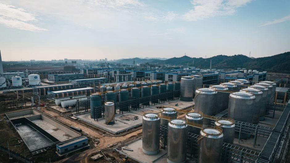
Lamella is the correct primary stage when the dominant contaminant is heavier than water, when the stream carries precipitated metals or dense fillers, and when capital and operator simplicity drive the decision. Trigger influent characteristics: heavy metal hydroxide sludges from plating-adjacent processes, pigment and filler-laden rinse water from coatings, grit and catalyst fines, and any high-density TSS stream without emulsified oils. These are the streams where gravity and inclined-plate hydraulics outperform microbubble attachment because the particles are already heavier than water and respond to polymer-assisted settling rather than bubble adhesion.
A lamella clarifier at 20–40 m/h surface loading delivers the same settling efficiency as a conventional rectangular basin in roughly one-third the footprint, and sludge recirculation improves floc density enough to cut polymer demand. There is no compressor, no saturator, no A/S ratio to maintain, and the controls are simple enough for an operator who is also running the reactor floor. CAPEX is lower than an equivalent DAF, and OPEX is lower on heavy, settleable solids where polymer is the main consumable. The HydropureWater high-efficiency lamella clarifier is the right primary stage for these streams and is typically paired with a plate-and-frame filter press for sludge dewatering to bring the 1–3% underflow solids up to a handleable cake.
For chemical plants with mixed influent — a coating line in the morning, a metal-precipitation batch in the afternoon — a single lamella is rarely enough. The decision framework below addresses that case directly.
The 2026 Decision Framework: A Weighted Matrix for Chemical Plants
The matrix below scores DAF and lamella clarifier on the criteria a Carol Stream plant actually faces: contaminant character, footprint, capital ceiling, operating tolerance, operator skill, and the regulatory target. Weights sum to 100; scores are 1–5 per criterion. Two worked examples follow — a surfactant batch plant and a metal-precipitation line.
| Criterion (weight) | DAF score | Lamella score | DAF weighted | Lamella weighted |
|---|---|---|---|---|
| TSS fraction and density (15) | 4 | 5 | 60 | 75 |
| FOG / emulsion load (20) | 5 | 2 | 100 | 40 |
| Metals precipitation (10) | 3 | 5 | 30 | 50 |
| Footprint available (10) | 5 | 4 | 50 | 40 |
| CAPEX ceiling (15) | 3 | 5 | 45 | 75 |
| OPEX tolerance (10) | 3 | 5 | 30 | 50 |
| Operator skill available (10) | 3 | 5 | 30 | 50 |
| 40 CFR Part 414 / 35 IAC 309 target (10) | 5 | 3 | 50 | 30 |
| Total (100) | 395 | 410 |
Worked example 1 — Surfactant batch plant (high FOG, low metals, tight footprint): reweight to FOG (30), footprint (20), 40 CFR Part 414 (20); DAF scores ~470, lamella ~310. DAF wins decisively, consistent with the case-study evidence that DAF achieves 95% FOG removal where clarifiers manage 70% on the same stream (commercial case study, 2026).
Worked example 2 — Metal-precipitation line (high TSS, heavy metal hydroxides, no oils): reweight to TSS (35), metals (25), CAPEX (20); lamella scores ~470, DAF ~300. Lamella wins on cost and on chemistry.
The hybrid path is the third option. A DAF primary stripping emulsions and FOG, feeding a lamella clarifier as a polish stage for any heavy solids that slip through, both discharging to a common sludge dewatering train. The hybrid case is also the right answer for a chemical plant with mixed influent — coating batches in the morning, metal-precipitation washes in the afternoon. The downstream gear that makes either path work is the same: a PLC-controlled coagulant and polymer dosing system ahead of the primary stage, and a plate-and-frame filter press for sludge dewatering downstream of both. For a benchmark on a parallel chemicals-industry decision in another region, see the parallel chemicals-industry DAF vs clarifier guide for Lakeland, FL.
Net 2026 stance: lamella clarifier wins on CAPEX and OPEX for heavy, settleable solids; DAF wins on total cost of ownership when oil or surfactant load drives compliance risk under 40 CFR Part 414; the hybrid DAF + lamella path covers mixed chemical streams where neither alone handles the full envelope. Pilot or jar testing on at least two representative batches is required before any capital commitment, and the dosing and dewatering gear should be specified in the same procurement package as the primary stage so the compliance story holds together end to end.
Frequently Asked Questions
Can a DAF and a clarifier be used together?
Yes. Hybrid DAF + lamella clarifier systems are common in chemical plants where DAF strips emulsions and FOG upstream and a lamella clarifier polishes heavy solids before biological treatment. The two units share a common sludge dewatering train and a common PLC-controlled dosing system, and the hybrid configuration handles mixed influent that neither unit could treat alone (per commercial hybrid case studies, 2026).
What removal efficiency should I expect on a chemical stream?
DAF achieves >90–95% FOG removal and 40–60% BOD reduction pre-biological on emulsified chemical streams. A lamella clarifier achieves 70–90% TSS removal depending on flocculation chemistry and plate spacing, and roughly 70% FOG on a stream dominated by oils — a measurable gap from DAF on the same influent. Always validate with jar testing or a pilot on at least two representative batches before specifying.
Which is more cost-effective in 2026?
Lamella clarifier wins on CAPEX and OPEX for heavy, settleable solids — no compressor, no saturator, lower polymer demand, simpler controls. DAF wins on total cost of ownership when oil or surfactant load drives compliance risk under 40 CFR Part 414 or 35 IAC Part 309, because the higher removal efficiency reduces downstream treatment burden and dewatering volume (per 2026 commercial case data).
How do I size the unit?
Match hydraulic loading to peak flow: 5–30 m³/m²·h for DAF (up to 40–50 with integrated plate packs) and 20–40 m/h surface loading for a lamella clarifier. Size for peak, not average, because batch dumps in chemical plants are what drive the compliance envelope. Validate the sizing with jar testing and, for flows above 50 m³/h or variable influent, run a 30–60 day pilot before committing capital.
What downstream equipment do I need?
Two items are non-negotiable for either path. A PLC-controlled coagulant and polymer dosing system ahead of the primary stage keeps floc condition stable across batch swings and protects the A/S ratio on a DAF. A plate-and-frame filter press downstream dewaters the 2–6% DAF float or the 1–3% lamella underflow to a handleable cake and reduces disposal cost. Specify both in the same procurement package as the primary stage.