What an Auckland Factory Actually Needs in 2026
An Auckland factory discharging to the Watercare sewer network in 2026 is bound by the Auckland Council Trade Waste Bylaw 2023, which sets default acceptance limits of BOD5 ≤ 300 mg/L, TSS ≤ 200 mg/L, NH4-N ≤ 50 mg/L, and pH 6–10 for trade waste entering the public wastewater system. Site-specific consent conditions — particularly for dairy processors around Manukau, meat and rendering operations in the Fonterra supply chain, and breweries — routinely tighten these to BOD5 ≤ 150 mg/L, TN ≤ 30 mg/L, and oil/grease ≤ 50 mg/L, and add E. coli and temperature triggers. Any packaged or containerised ETP must be designed against the strictest version of those numbers, not the bylaw default.
The dominant industrial effluent profiles in Auckland fall into four streams: dairy and milk powder processing (high FOG, lactose BOD, CIP chemical peaks), meat and rendering (high protein BOD, blood solids, slaughter-line surge flows), brewing and beverage (variable organic load, caustic washwater, low pH spikes), and metal finishing or food oils (emulsified oils, hexavalent chromium in some sites). Each of these drives different DAF chemistry — coagulant choice, flocculant dose, and pH correction — but all four share a common need: gross contaminant and suspended-solids removal before any biological stage sees the water.
The 2026 baseline answer is a treatment train running DAF → biological (MBR or MBBR) → tertiary filtration → disinfection, with reverse osmosis added where reuse is economically justified. The reference benchmark is the ShubhLaxmi 1.2 MLD ETP — a DAF + MBR + 2-stage RO configuration delivering 90% water recovery (per the 2025 commissioning case study, Unitop Aquacare). Translated to South Auckland conditions, the same architecture can cut a 1,200 m³/day factory's trade-waste volume by roughly two-thirds and offset Auckland's high discharge tariffs, where Watercare trade-waste charges rank among the steepest in New Zealand. The rest of this article sizes each unit, sets realistic NZD cost bands, and closes with a vendor shortlisting checklist.
Why DAF Is the First Unit in Almost Every Auckland Industrial ETP
A dissolved air flotation system removes 90–95% of TSS, FOG, and colloidal solids in a single pass, which is why it sits at the head of nearly every food, dairy, and meat effluent train in Auckland. The unit works by saturating a side-stream of clarified water with air at 4–6 bar, then releasing that pressure through a let-down valve at the DAF inlet. The sudden depressurisation generates a cloud of 10–80 µm micro-bubbles that attach to flocculated oil droplets and suspended particles, lifting them to the surface as a float layer. A chain-and-scraper mechanism sweeps the float into a scum hopper, while clarified water passes through a lamella separator that increases the effective settling area for any heavier solids that slip past the float zone, which then drop into a sediment hopper for sludge processing. The treated underflow exits over an effluent weir into the downstream biological or polishing stage.
Hydraulically, a DAF runs at a 3–5 minute residence time and an air-to-solids ratio in the standard engineering range of 0.005–0.06 lb air per lb solids — wide enough that the exact value is set by jar testing on the actual waste, not by the supplier's catalogue. Because the DAF strips FOG, protein, and colloids upfront, the downstream MBBR or MBR sees a far more stable influent, which is what lets the biological stage reliably hit the 30–50 mg/L NH4-N consent targets that Auckland's stricter site-specific conditions impose.
For Auckland plant sizes, the DAF system covers 4–300 m³/h across 13 standard models. Small food and beverage plants typically fall in the 4–25 m³/h band; mid-sized dairy, meat, and brewing sites land at 50–100 m³/h; large breweries, milk powder, and rendering plants run 150–300 m³/h, sometimes with two units in parallel for redundancy. Anything below 50 m³/h is usually containerised, which matters in South Auckland where indoor floor space is at a premium.
Sizing the DAF and the Downstream Treatment Train for Auckland Conditions
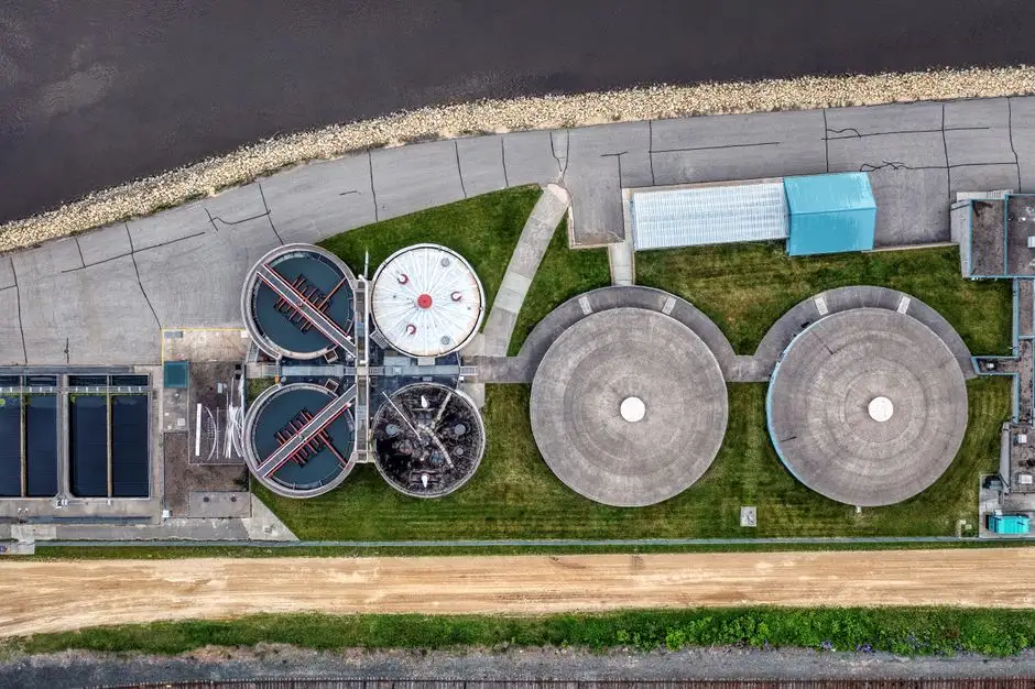
Sizing an industrial ETP for Auckland is a six-step exercise, and skipping any step is the most common reason plants fail their consent review. Use this as a working sequence before you call any vendor.
- Establish design flow. Take the average daily discharge, then apply a peak factor of 1.5–2.0× to capture CIP wash cycles, slaughter-line batch peaks, and brewery kettle drops. Under-sizing this number is the single most common DAF failure mode.
- Select the DAF model. Match peak flow against the sizing table on the DAF system product page, then upsize by at least one model for the float layer and scum handling volume.
- Choose the biological stage. MBBR handles standard BOD and ammonia reduction; for sites targeting water reuse, an integrated MBR system is preferred because its effluent carries TSS below 1 µm, which protects the downstream RO membranes from fouling.
- Add tertiary filtration. A multi-media filter polishes residual TSS to <5 mg/L before the RO feed, extending membrane life and reducing CIP frequency.
- Install disinfection. UV handles primary kill; for residual disinfection across a long trade-waste line, a chlorine dioxide generator (50–20,000 g/h) scales to any industrial flow without the bromate formation risk of straight chlorine.
- Plan sludge handling. Route DAF scum and biological waste to a plate and frame filter press (1–500 m² filtration area) to drop cake solids to 25–35% DS before offsite disposal, which materially reduces sludge haulage cost in the Auckland region.
For plants that need the reuse step, a two-stage RO achieves 95% recovery in the standard configuration and 90% in a DAF + MBR + RO train like the ShubhLaxmi reference plant. Cold-weather design is non-negotiable in Auckland: winter ground-water temperatures drop to 12–15°C, which slows nitrification kinetics and means the biological stage needs 25–40% more volume than a tropical design at the same loading.
| Stage | Primary Function | Typical Removal / Spec | Auckland Design Note |
|---|---|---|---|
| DAF | FOG + TSS + colloidal removal | 90–95% TSS, 95%+ oil/grease | Size for 1.5–2.0× peak; SS316 for salty/brewery streams |
| MBR | BOD + NH4-N + TN reduction | Effluent TSS <1 mg/L; NH4-N <5 mg/L | Upsize for 12–15°C winter operation |
| Multi-media filter | TSS polish before RO | TSS <5 mg/L | Sand + anthracite + garnet, automated backwash |
| RO (2-stage) | Dissolved salts + reuse | 95% recovery, 99% rejection | Energy recovery turbine on stage 2 |
| ClO₂ / UV | Disinfection + residual | E. coli <100 CFU/100 mL | ClO₂ preferred over Cl₂ for ammonia-rich streams |
| Plate and frame press | Sludge dewatering | Cake 25–35% DS | 1–500 m² models; reduces Auckland haulage cost |
Choosing the Right DAF Variant: Round vs Lamella vs High-Rate for Auckland Sites
Not all DAFs are the same, and the wrong configuration is the leading cause of ETP failure on Auckland dairy sites — usually because the air-saturation pump is undersized and the scraper is under-rated for the float load. Three configurations dominate the market, and each maps to a different Auckland footprint and chemistry profile.
The traditional round DAF offers the longest track record, the most forgiving hydraulics, and the easiest scum handling, but it has the largest footprint — typically 8–12 m² per 25 m³/h of capacity. The lamella-assisted DAF adds inclined plates inside the clarification zone, roughly doubling the effective settling area in the same tank, which makes it a better fit for plants with constrained indoor space. The high-rate compact DAF trades some float-solids capacity for a 40–60% smaller footprint and is the default for containerised skids shipped to South Auckland food plants. In all three variants, a poorly chosen unit shows up as a thin, watery float layer and rising effluent TSS within weeks of start-up.
For polishing behind a biological stage, a lamella clarifier runs at 20–40 m/h surface loading rate and can cut coagulant chemical use by about 30% compared with a conventional settler — useful when the upstream MBR effluent already carries low TSS and the clarifier is acting as a guard filter before RO. Auckland-specific build specifications to insist on: SS316 wetted parts where effluent is salty or brewery-derived, seismic bracing to NZS 1170.5 for South Auckland sites, and IP65-rated control panels to handle the humid coastal environment.
| Configuration | Footprint (relative) | Best Hydraulic Loading | Scum Dryness | Typical CAPEX vs Round DAF |
|---|---|---|---|---|
| Round DAF (traditional) | 1.0× (baseline) | 15–25 m/h | 4–6% DS | 1.0× (baseline) |
| Lamella-assisted DAF | 0.7–0.8× | 20–30 m/h | 4–5% DS | +10–20% |
| High-rate compact DAF | 0.4–0.6× | 25–40 m/h | 3–5% DS | +15–30% |
Auckland ETP Cost Benchmarks and 2026 CAPEX/OPEX Reality
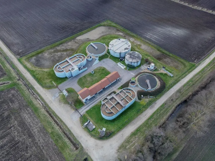
Realistic 2026 engineering estimates for installed industrial ETP cost in New Zealand, presented as order-of-magnitude bands rather than firm quotes, because site conditions, seismic bracing, and consenting drive wide variance:
| Plant Size | Typical Configuration | Indicative CAPEX (NZD) | Dominant OPEX Drivers |
|---|---|---|---|
| Small (≤50 m³/day) | Containerised DAF + MBR + UV | NZ$250,000 – 600,000 | Power, coagulant/flocculant, sludge haulage |
| Mid (200 m³/day) | DAF + MBR + multi-media + ClO₂ | NZ$1.0M – 2.5M | Aeration power, membrane replacement, trade-waste tariff |
| Large dairy (1,000–1,200 m³/day) | DAF + MBR + 2-stage RO + sludge press | NZ$3.0M – 7.0M | RO membrane replacement, high-pressure pumping, sludge disposal |
Power is the single largest OPEX line, and aeration typically accounts for 50–60% of total electricity use on a biological ETP; specifying high-efficiency blowers and variable-frequency drives on the DAF recycle pump is the fastest payback. Chemical dosing for DAF (typically a coagulant such as PAC or ferric chloride plus a polyacrylamide flocculant) runs NZ$0.05–0.20 per cubic metre treated, depending on influent FOG. Sludge haulage to a Class A landfill in the Auckland region is one of the more volatile cost lines in 2026 and is the strongest economic argument for an on-site plate and frame filter press — every 10% improvement in cake dryness roughly halves the volume sent offsite.
The reuse case is where Auckland diverges from most other New Zealand regions. A 90% recovery RO train (per the ShubhLaxmi 1.2 MLD benchmark) can offset Watercare's trade-waste volume charges, which sit toward the top of the New Zealand tariff range, with payback periods commonly falling into the 3–5 year window for high-discharge dairy and meat sites. Containerised plug-and-play systems cut civil works and install time by 4–8 weeks versus a stick-built equivalent, which matters when consent deadlines are tight.
Supplier Checklist: How to Evaluate a 2026 Auckland DAF and ETP Vendor
Procurement teams in Auckland regularly receive quotes that differ by 2–3× for what looks like the same plant, so the evaluation needs to be technically anchored, not price-anchored. Run each candidate through the following seven-point checklist before signing a purchase order.
- Hydraulic and contaminant-based sizing. The supplier must size the DAF against your peak flow, FOG load, and TSS — not against a generic model number from a catalogue. Ask for the calculation sheet.
- Material specification. SS304 minimum on wetted parts; SS316 mandatory for salty streams, brewery effluent, or coastal sites. Anything else is a corrosion risk in the humid Auckland air.
- PLC/SCADA and remote monitoring. Confirm Modbus TCP or Ethernet/IP integration with the plant's existing system, and remote access for the supplier's service team. Without this, fault response is always slower than it needs to be.
- Documentation and quality systems. FAT records, CE marking, ISO 9001 certification, and reference sites in dairy, meat, or brewing — not just generic "food and beverage".
- Local commissioning and after-sales. An NZ-based commissioning engineer or a documented local service partner. A 48-hour SLA on response time should be written into the contract.
- Performance warranty. A 12-month warranty tied to discharge numbers (BOD5, TSS, NH4-N at the consent point), not just equipment warranty. Vendors who refuse this clause usually know their sizing is optimistic.
- Chemical dosing integration. A bundled PLC-controlled chemical dosing skid sized for your actual coagulant and flocculant consumption — dosing is where most underperforming DAFs are actually failing.
For deeper DAF-specific selection criteria, the best DAF unit engineering spec guide walks through model selection in more detail, and the DAF buyer's guide covers the commercial terms to negotiate. For meat plants specifically, the slaughterhouse DAF pretreatment article addresses the FOG and blood-solids load profile that generic guides miss.
Frequently Asked Questions
What size DAF do I need for X m³/day?
As a rule of thumb, size the DAF for 1.5–2.0× your average daily flow to handle peak events such as CIP wash cycles or slaughter-line batches. A plant discharging 100 m³/day average should therefore be sized for 150–200 m³/day, which maps to a DAF model in the 8–12 m³/h range running 18–24 hours, or a larger unit on a shorter duty cycle. The exact DAF model still depends on FOG and TSS load, not just flow, so jar testing on your actual waste is non-negotiable.
How much does an industrial ETP cost in New Zealand in 2026?
Indicative CAPEX ranges from NZ$250,000–600,000 for a small containerised DAF + MBR (≤50 m³/day), NZ$1.0M–2.5M for a mid-sized 200 m³/day system with tertiary filtration, and NZ$3.0M–7.0M for a large dairy or meat plant at 1,000–1,200 m³/day including RO. These are engineering estimates only — site conditions, seismic requirements, and consenting all move the number materially. OPEX is dominated by aeration power (50–60% of electrical OPEX) and sludge haulage.
What are the Auckland Trade Waste discharge limits for industry?
Under the Auckland Council Trade Waste Bylaw 2023, default sewer-discharge limits are BOD5 ≤ 300 mg/L, TSS ≤ 200 mg/L, NH4-N ≤ 50 mg/L, pH 6–10, and oil/grease ≤ 100 mg/L. Site-specific consents — common for dairy, meat, and brewing — are typically tighter, with BOD5 ≤ 150 mg/L, TN ≤ 30 mg/L, oil/grease ≤ 50 mg/L, and E. coli limits added. Always confirm the current consent conditions with Watercare before sizing the ETP.
DAF vs API separator — which is better for Auckland sites?
For most Auckland food, dairy, and meat applications, DAF is the better choice because it removes emulsified oils and colloidal solids that an API separator cannot, and it does so in a fraction of the footprint. API separators are still used for bulk free-oil removal in refineries, but for trade-waste compliance in Auckland they are typically followed by a DAF anyway. The full head-to-head is covered in our DAF vs API separator comparison.
Can I reuse treated wastewater in my Auckland factory?
Yes. A DAF + MBR + 2-stage RO train can achieve 90% water recovery, per the ShubhLaxmi 1.2 MLD reference plant commissioned in 2025. For an Auckland dairy or meat site, that typically means reuse for CIP rinsewater, boiler feed (with further polishing), cooling tower make-up, or yard washdown. The economics work because Watercare trade-waste tariffs are among the highest in New Zealand, which shortens the RO payback period to a 3–5 year window on most high-discharge sites.