Why Battery Gigafactory Wastewater Is a Unique Engineering Challenge
Lithium-ion cell production generates four chemically distinct wastewater streams that cannot be treated as a combined flow: cathode coating wash water (carrying N-methyl-2-pyrrolidone solvent and PVDF binder residues), anode coating wash water (CMC/SBR binder in aqueous slurry), electrolyte salt flush (LiPF₆ hydrolysis releases fluoride and phosphate), and general plant effluent (boiler blowdown, HVAC condensate, domestic sewage). Concentrated cathode coating wastewater typically runs COD 5,000–25,000 mg/L, fluoride 50–500 mg/L, suspended solids 500–3,000 mg/L, and pH 2–4 — well outside the envelope of a generic industrial WWTP. Source segregation drives the entire train economics: mixing the NMP-bearing cathode stream with general effluent destroys solvent-recovery value and pushes the fluoride load past the precipitation capacity of any downstream calcium dose. CATL's global footprint — a 14 GWh German plant and the Debrecen gigafactory under construction in Hungary (per ACS coverage, 2026) — means the wastewater volumes for a 100+ GWh global production network sit in the range of several thousand m³/day per site, which is why the treatment train must be engineered as a chemical-recovery plant first and a discharge plant second.
Step 1 — Source Segregation and Equalization
The front-end of a gigafactory wastewater train is segregated collection, not commingled flow. Each of the four streams drains to its own sump, with pH correction to 6–8 using NaOH or lime before the equalization basin — bringing the cathode stream out of its native pH 2–4 range and stopping fluoride volatilization as HF. Equalization basins are sized for 8–24 hours hydraulic retention at peak wet-weather flow, with mechanical mixers homogenizing pH, temperature, and COD swings from batch coating operations. Coarse screening ahead of the equalization pumps is provided by a 2–5 mm aperture rotary mechanical bar screen, which protects downstream sludge-handling equipment from coating-defect scraps and separator film fragments. Online instrumentation (pH, conductivity, fluoride-ion selective electrode, TOC) feeds the automatic dosing system; without that feedback loop the equalization basin is just a buffer, not a process node.
Step 2 — NMP Recovery from Cathode Coating Wastewater
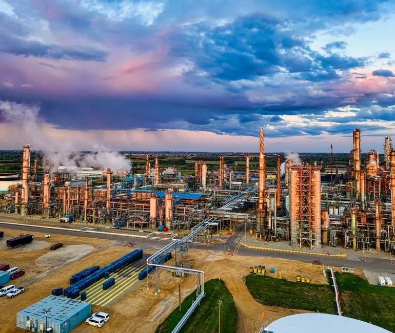
Cathode coating wastewater is the single most valuable stream in the train because it contains NMP at roughly 1–5 wt% — and NMP trades at $2,000–3,000/t (2026 market range), so recovery is a margin line, not a treatment cost. Vacuum distillation at 50–100 mbar and 80–120 °C concentrates the dilute NMP back to >99.5% reusable grade, which is returned directly to the cathode slurry mixing stage and qualifies as a closed-loop material under the recycled-content accounting of EU Battery Regulation 2023/1542. Pre-treatment ahead of the distillation column is mandatory: pH adjustment, suspended solids removal in a high-efficiency sedimentation tank (lamella clarifier), and activated-carbon polishing to strip PVDF binder residues that would otherwise foul the reboiler. The automatic chemical dosing system holds pH within the tight band the column needs. Membrane separation (NF/RO) is not a viable alternative — NMP passes to permeate and fouls the membrane within hours, and biological treatment chokes above ~2,000 mg/L solvent, killing the biomass entirely.
Step 3 — Heavy Metal Precipitation and Coagulation
After NMP recovery, the cathode stream still carries dissolved Ni, Co, Mn, Li, and 50–500 mg/L fluoride. The removal train is staged pH precipitation: Ni and Co drop out as hydroxides at pH 9.5–10.5, Mn requires pH 10+ plus an oxidant dose (NaClO or KMnO₄) to convert soluble Mn²⁺ to insoluble MnO₂, and lithium stays in solution — it does not precipitate at any practical pH and reports to the RO concentrate downstream. Fluoride is removed by CaCl₂ dosing to precipitate CaF₂ (Ksp ≈ 3.9×10⁻¹¹), with a target residual below 10 mg/L to meet China GB 30485-2013 and EU IED 2010/75/EU BAT-AEL for non-ferrous metals. Coagulation uses PAC at 50–200 mg/L plus anionic polyacrylamide at 1–5 mg/L, with a dissolved air flotation system handling the lighter floc and a lamella clarifier handling denser hydroxide sludge. Chemical dose is held by the automatic chemical dosing system tied to the online fluoride and pH probes. Hydroxide sludge is dewatered on a plate and frame filter press to a 25–35% dry solids cake routed to licensed hazardous-waste disposal or to a metal-recovery off-taker.
| Parameter | Influent (post-NMP recovery) | After Stage 1 (pH 9.5–10.5) | After Stage 2 (CaCl₂ + Mn oxidation) | Discharge Target |
|---|---|---|---|---|
| Ni | 50–200 mg/L | <0.5 mg/L | <0.5 mg/L | <0.5 mg/L (GB 30485-2013) |
| Co | 20–100 mg/L | <1.0 mg/L | <1.0 mg/L | <1.0 mg/L (BAT-AEL) |
| Mn | 10–50 mg/L | 5–20 mg/L | <2 mg/L | <2 mg/L (BAT-AEL) |
| F⁻ | 50–500 mg/L | 50–500 mg/L | <10 mg/L | <10 mg/L (GB 30485-2013) |
| Li⁺ | 20–100 mg/L | 20–100 mg/L (soluble) | 20–100 mg/L (reports to RO) | — (recovered in ZLD) |
| pH | 6–8 | 9.5–10.5 | 8–9 (re-neutralized) | 6–9 |
Step 4 — Biological Treatment and Membrane Bioreactor (MBR) Polishing
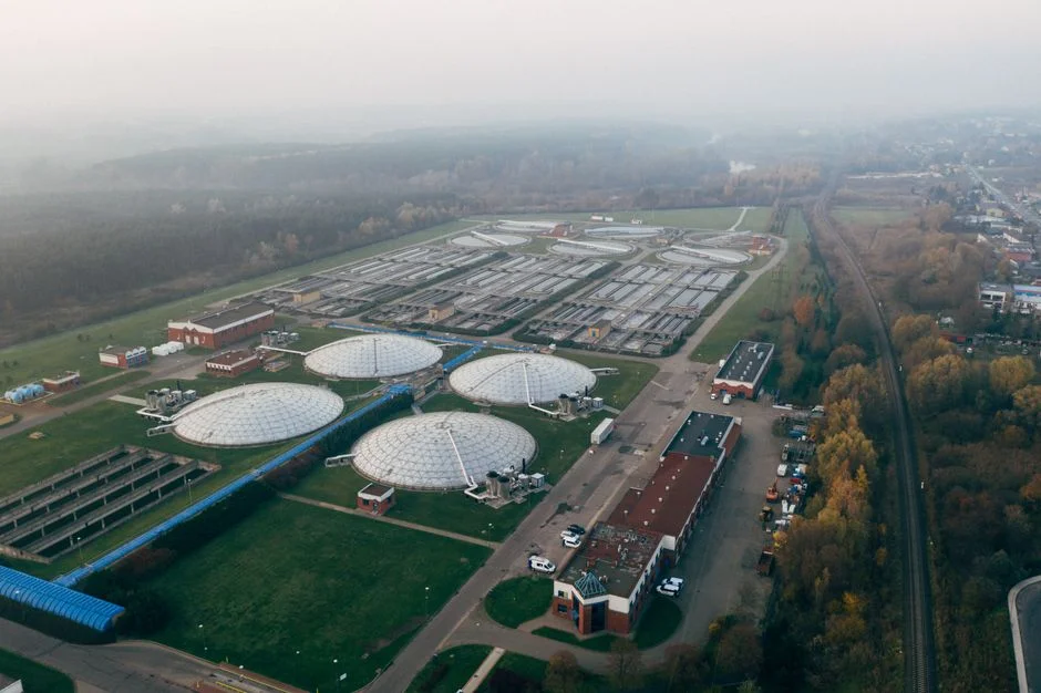
The pretreated streams — combined with the lower-strength anode and electrolyte effluents — enter biological treatment for residual COD and ammonia. An A²/O (anaerobic/anoxic/aerobic) configuration or a sequencing batch reactor delivers 90–95% COD removal and total nitrogen below 15 mg/L at typical operating parameters of MLSS 8,000–12,000 mg/L, HRT 12–24 hours, and SRT 20–40 days. The MBR step replaces the conventional secondary clarifier: submerged PVDF membranes at 0.1–0.4 μm cut TSS below 1 mg/L and SDI below 3, which is the threshold for RO membrane protection. Membrane air-scour is set at 0.3–0.5 Nm³/hr per m² of membrane area to control fouling without excessive aeration energy. The MBR permeate is reused directly as cooling-tower makeup, toilet-flush water, and landscape irrigation — typically a 30–50% reduction in plant freshwater demand. For related reuse logic in a different effluent class, the electronics wastewater ZLD blueprint walks the same MBR-to-RO handoff in semiconductor fabs.
| Parameter | MBR Influent | MBR Permeate | RO Feed Limit |
|---|---|---|---|
| COD | 500–2,000 mg/L | <50 mg/L | <30 mg/L |
| TN (as N) | 40–100 mg/L | <15 mg/L | — |
| TSS | 200–1,000 mg/L | <1 mg/L | <1 mg/L |
| SDI₁₅ | — | <3 | <3 |
| Turbidity | — | <1 NTU | <1 NTU |
The MBR membrane bioreactor system and the MBR membrane module are the standard packaged delivery for this duty class.
Step 5 — Reverse Osmosis and Water Reuse
RO is the closure of the water-reuse loop, and its feed must meet three hard limits: SDI <3, free chlorine <0.1 mg/L, and Fe <0.05 mg/L. Pretreatment is cartridge filtration at 5 μm plus antiscalant dosing ahead of the high-pressure pump, with a multi-media filter as the workhorse for turbidity and iron reduction. Recovery is set at 70–80% — higher recovery saves water but raises concentrate TDS past what the downstream MVR can crystallize economically. Permeate conductivity runs below 50 μS/cm, suitable as RO permeate for ultrapure water pre-feed or direct cooling-tower reuse. The 20–30% concentrate is a high-salinity brine routed to the ZLD evaporator, and that concentrate stream is also where the lithium in the system accumulates. For the broader question of how oily or process streams integrate with the membrane train, the oily wastewater treatment guide covers the comparable pretreatment logic. The industrial RO system delivers this step at the flows required for a 100 GWh-class site.
Step 6 — Zero Liquid Discharge and Lithium Recovery
The RO concentrate is the final liquid stream to handle, and mechanical vapor recompression (MVR) is the only commercially proven route to zero liquid discharge at gigafactory scale. MVR electrical consumption sits at 20–35 kWh per m³ of distillate (HydropureWater field data, 2026), producing reuse-grade distillate and a concentrated brine at 200,000–250,000 mg/L TDS that feeds a forced-circulation crystallizer. The crystallizer yields a Na₂SO₄/NaCl mixed salt cake for licensed disposal, and — critically — a lithium-enriched mother liquor that can be routed to a downstream Li₂CO₃ precipitation stage. This is where the wastewater train flips from a cost center to a strategic asset: EU Battery Regulation 2023/1542 sets 2031 recycled-content targets of 16% for Co, 12% for Ni, and 6% for Li, and direct lithium recovery from process brine is one of the few routes that counts toward that target. The overall plant water balance closes at 70–90% reuse water, with the remaining 10–30% leaving the site as a solid salt cake. For heavy-metal compliance thresholds that govern that salt cake's disposal route, the lead and heavy metal discharge standard guide is the right reference. For CAPEX-class benchmarking on a comparable fab wastewater plant, the chip fab wastewater treatment plant guide provides a useful cost-band reference.
Frequently Asked Questions
What is the first step in treating cathode coating wastewater at a gigafactory?
Source segregation and pH correction to 6–8 with NaOH or lime, followed by 8–24 hours of equalization to homogenize batch swings. Only then does the stream enter NMP recovery by vacuum distillation at 50–100 mbar and 80–120 °C, where 1–5 wt% NMP is concentrated back to >99.5% reusable grade for direct return to the cathode slurry mixing stage.
How is fluoride removed from lithium battery manufacturing effluent?
Calcium chloride dosing precipitates fluoride as CaF₂ (Ksp ≈ 3.9×10⁻¹¹), with a target residual below 10 mg/L to satisfy both China GB 30485-2013 and EU IED 2010/75/EU BAT-AEL. The CaCl₂ dose is typically staged after the heavy-metal hydroxide precipitation step to avoid fluoride being carried into the metal-hydroxide sludge.
Why is MBR used instead of a conventional clarifier before RO?
Submerged PVDF MBR membranes at 0.1–0.4 μm cut TSS below 1 mg/L and SDI below 3, which is the feed-quality threshold for RO membrane protection. Conventional clarifiers in this duty class struggle to hold SDI below 5 reliably, and the cost of replacing fouled RO membranes far exceeds the incremental capex of an MBR.
Can lithium actually be recovered from battery gigafactory wastewater?
Yes — lithium stays soluble through hydroxide precipitation and concentrates in the RO reject, which feeds an MVR evaporator and forced-circulation crystallizer. The lithium-enriched mother liquor is then precipitated as Li₂CO₃, and this recovered lithium counts toward the 6% Li recycled-content target set by EU Battery Regulation 2023/1542 for 2031.