Why Activated Sludge Still Dominates Industrial Plants
Conventional activated sludge remains the most widely used industrial water treatment system in 2026, with CWT-Global describing it as among the most common types in both municipal and industrial plants. Its dominance comes from two engineering properties: adaptability to varying wastewater loads and lower cost versus more advanced membrane and polishing systems. The biology is suspended-growth, meaning free-floating microorganisms metabolize dissolved and particulate organics in an aeration basin, and the mixed liquor then separates from the clarified effluent in a downstream settler.
For an EPC specifier, the practical meaning of "adaptable" is that the same reactor envelope can be re-rated by changing MLSS, F/M ratio, or SRT to handle a food plant one year and a pharmaceutical site the next, without redesigning civil works. The process also scales across facility sizes, which is why it shows up in everything from a 50 m³/d specialty chemical line to a 50,000 m³/d textile complex.
Activated sludge has well-known limits that the engineer must respect. It reduces organics and suspended solids, but it does not remove dissolved salts, does not handle high FOG (fats, oils, grease) loads without upstream flotation, and does not strip trace organics, heavy metals, or refractory COD. Those duties belong to flotation, membrane, and chemical unit operations downstream. Where reuse intent or a tight discharge cap pushes the effluent specification beyond what a clarifier can produce, an integrated MBR membrane bioreactor system takes the same biology and adds an absolute physical barrier.
Six Industrial Treatment Systems at a Glance
The table below covers the six unit operations most often specified in industrial tenders in 2026: conventional activated sludge, MBR, DAF, lamella clarification, UF, and RO. The underlying sequence is preliminary → primary → secondary → tertiary → disinfection, per CWT-Global, and each system below sits in one or more of those stages. Read the table as a duty-to-system map, not as a ranking; an MBR outperforms a clarifier on reuse quality, and a clarifier outperforms an MBR on FOG-heavy influent. The columns used here match the duty a procurement engineer needs to map to a P&ID (piping and instrumentation diagram): primary removal target, stage in the train, typical industrial feed, and a one-line "when to pick it" trigger.
| System | Primary duty | Stage in train | Typical industrial feed | When to pick it |
|---|---|---|---|---|
| Conventional activated sludge | BOD/COD reduction, nitrification | Secondary | Food, pharma, textile, general organics load | Default for organics; scales with load changes |
| MBR (membrane bioreactor) | BOD/COD + TSS absolute barrier | Secondary + tertiary | Sites with limited footprint or reuse intent | Near-reuse effluent or strict discharge BOD/COD |
| DAF (dissolved air flotation) | FOG, floatables, emulsions, colloids | Primary / pre-biological | Food, dairy, meat, refinery, metalworking | High oil, grease, or floatable load upstream of biology |
| Lamella clarifier | Density-driven TSS reduction | Primary / tertiary | General industrial, metal finishing, mining | Where settling dominates and coagulant cost matters |
| UF (ultrafiltration) | Colloids, bacteria, turbidity, SDI reduction | Tertiary / RO pretreatment | Pharma, food, reuse loops, cooling makeup | Protect RO, or partial reuse without ion removal |
| RO (reverse osmosis) | Dissolved ions, salts, trace contaminants | Tertiary / polishing | Boiler feed, ZLD, semiconductor, pharma | Required when dissolved salts must be removed for reuse |
Per CWT-Global, the underlying treatment sequence (preliminary → primary → secondary → tertiary → disinfection) is consistent across these systems, and each row in the table maps to one or more of those stages. Use the duty column, not the row order, to drive selection.
MBR Membrane Bioreactor: The Compact Reuse-Grade Option

An MBR couples activated-sludge biology with a submerged ultrafiltration membrane, replacing the conventional clarifier with an absolute barrier. The biological duty is identical to a standard aeration tank, so influent character and MLSS setpoints transfer directly; what changes is the solids separation step. Effluent TSS is no longer a function of sludge settleability, which removes one of the largest failure modes of a conventional activated-sludge plant: the bulking sludge that sends TSS over the discharge limit on a Tuesday afternoon.
For an industrial buyer, the key parameters to specify are membrane material, nominal pore size, flux, and aeration scouring. The HydropureWater MBR flat-sheet module uses PVDF (polyvinylidene fluoride) membranes at 0.1 μm nominal pore size with integrated aeration scouring, and individual elements are replaceable so a single damaged sheet does not force a full rack swap. In the broader integrated MBR membrane bioreactor system, the same module sits inside a packaged or skid-mounted reactor with screens, blowers, and a CIP (clean-in-place) loop pre-wired. The article on HydropureWater's MBR flat-sheet module covers the DF series details for an engineer mid-spec.
| Parameter | DF series specification | Selection note |
|---|---|---|
| Membrane material | PVDF | Chemical resistance for CIP with NaOCl / citric acid |
| Nominal pore size | 0.1 μm | Absolute barrier for bacteria and most colloids |
| Aeration scouring | Integrated | Controls fouling between relaxation cycles |
| Element replacement | Individual sheets replaceable | Lower lifetime cost vs full-rack swap |
Fit an MBR to a site when land is tight, when the discharge contract requires very low BOD/COD/TSS, or when the effluent is destined for washwater, irrigation, or cooling-tower makeup. CWT-Global frames advanced systems as costlier than conventional, which is the honest trade-off: membrane replacement and aeration energy are higher than for a clarifier, so size the duty and confirm the Opex (operating expenditure) line before selecting. For flux, SRT (solids retention time), and aeration setpoints in 2026, the 2026 MBR module design criteria guide is the next read.
DAF and Lamella Clarifiers: Pretreatment Workhorses
DAF and lamella clarifiers compete for the primary-solids-removal slot in the train, and the choice is driven by influent character more than by manufacturer preference. DAF injects saturated water at system pressure, releasing it through needle valves or special nozzles at atmospheric pressure; the resulting micro-bubbles attach to suspended solids, FOG, oils, and colloids and float them to the surface for automatic skimming. It is the workhorse for food, dairy, meat, pulp & paper, refinery, and metalworking duties, where the floatable fraction dominates the load. The HydropureWater DAF system is rated across those sectors and integrates with downstream biology.
Lamella clarification uses inclined plates at 55–60° to shorten the settling path of suspended solids. The effective settling area is multiplied by the plate count, so a small footprint can handle a high surface overflow rate. Coagulant consumption drops because flocs only need to settle the short distance between plates rather than the full clarifier depth. The HydropureWater lamella clarifier is the standard pick for sites where the solids are density-driven rather than floatable, including metal finishing, mining runoff, and general industrial washwater. Per CWT-Global, preliminary and primary stages exist to remove debris, grit, and solids that would otherwise damage downstream equipment; DAF and lamella are the modern industrial expressions of that stage.
Decision logic for the specifier: choose DAF when FOG, free oil, or floatable colloids are a measurable fraction of the load; choose lamella when the solids settle on their own and coagulant cost is a concern; choose DAF with a coagulant stage when the FOG is emulsified and the emulsion must be broken chemically first. For sector-specific sizing, the Kyushu semiconductor case study (DAF vs clarifier selection) and the food & beverage selection guide are useful reference points when a tender crosses both duty types.
UF and RO: Membrane Polishing for Reuse and High-Purity Process Water
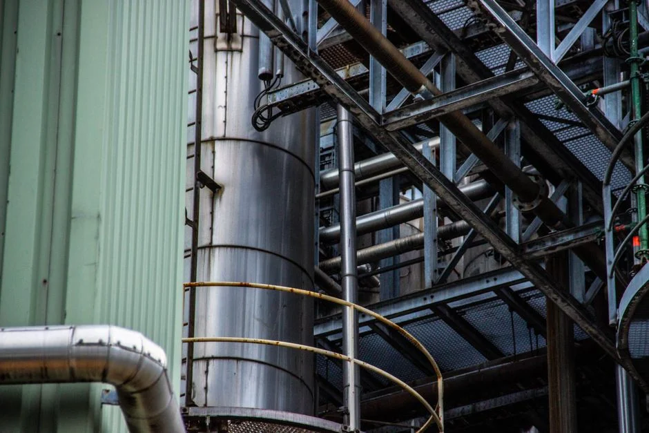
UF and RO are the two membrane technologies that engineers most often confuse, and they are not interchangeable. Ultrafiltration is a low-pressure membrane process that removes suspended solids, colloids, bacteria, and some viruses on a size-exclusion basis; it does not remove dissolved ions. Reverse osmosis is a high-pressure process that rejects dissolved salts and small organics by diffusion through a dense membrane; it does not, on its own, handle a high-TDS (total dissolved solids) feed without pretreatment.
The HydropureWater UF system uses 0.03 μm PVDF hollow-fiber membranes, accepts turbid feed up to 300 ppm with automatic backwash and air scour, and runs as a chemical-free barrier. That makes it the right choice for RO protection, for partial reuse without ion removal, and for any duty where turbidity or SDI (silt density index, a measure of fouling potential) is the controlling parameter. The HydropureWater UF system integrates with upstream screens and downstream tanks for a packaged skid.
The HydropureWater industrial RO system runs at recovery rates up to 95% and produces ultra-pure permeate for pharmaceutical, semiconductor, food & beverage, and power duties, with fully automated operation and continuous output. Recovery is the fraction of feed water that becomes permeate; higher recovery means less reject but also higher scaling risk on the membrane tail element, which is why RO is always sized against a feedwater analysis rather than a generic flow. The HydropureWater industrial RO system is the correct selection when the duty is boiler feed, process water, or any zero-liquid-discharge (ZLD) scheme. Both belong in the tertiary stage of the CWT-Global sequence, downstream of biological and clarification steps. For retrofits, the HydropureWater membrane elements and pressure vessels line supports any major OEM, which matters when an existing plant is being re-rated rather than built new.
Chemical Dosing, Disinfection and Sludge Handling
Supporting unit operations close the train, and a tender that omits them is incomplete. Automatic chemical dosing provides PLC-controlled injection of coagulants, flocculants, pH adjusters, and specialty chemicals; the HydropureWater dosing skid ties directly into DAF and lamella performance because both rely on correct coagulant stoichiometry. Without a dosing package, the upstream flotation or settling stage drifts off design and the biological stage inherits the shock.
Disinfection is the final effluent barrier before discharge or reuse, and CWT-Global describes it as vital for eliminating pathogens, with method selection driven by effluent quality and environmental impact. UV sterilizers deliver chemical-free disinfection and are effective against chlorine-resistant organisms, including Cryptosporidium and Giardia, which chlorination handles poorly. The HydropureWater UV sterilizer is sized to the peak post-MBR or post-RO flow. For higher-volume industrial effluent and hospital waste streams where residual chlorine is required, the HydropureWater chlorine dioxide generator covers the duty.
Sludge dewatering via plate and frame filter press closes the mass balance, with filtration areas and PLC options matched to the upstream clarifier or DAF. The HydropureWater plate and frame filter press handles the solids stream that the rest of the train produces; without it, the plant creates a downstream solids problem that the regulator will eventually see. A rotary mechanical bar screen at the head of the train protects pumps, valves, and downstream biology from debris that would otherwise accumulate and damage equipment. For the parameter side of organics and suspended solids removal, the 2026 COD and SS removal guide ties the chemical dosing step to measurable effluent targets.
A 2026 Selection Framework for Industrial Plants
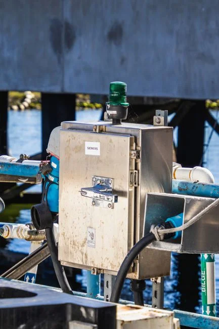
Selection in 2026 is duty-driven, not vendor-driven. Match the contaminant to the system: organics and BOD go to activated sludge or MBR; FOG and floatables go to DAF; density-driven solids go to lamella; colloids and bacteria go to UF; dissolved ions go to RO; pathogens go to UV or ClO₂ (chlorine dioxide). This is consistent with the CWT-Global stage sequence and with the unit-operation roles in the table above.
Stage sequencing must be respected. A rotary bar screen precedes everything, because debris that reaches a pump or a membrane element is a forced outage. After screening, grit removal and flow equalization sit ahead of the biological stage, which sits ahead of the tertiary polishing stage, which sits ahead of disinfection. Skipping or reordering a stage pushes the same removal burden onto a downstream unit and increases both CAPEX (capital expenditure) and Opex.
Reuse intent is the single largest 2026 selection lever. If the goal is ZLD or process reuse, RO enters the train earlier and UF becomes mandatory as RO pretreatment. If the goal is sewer discharge under standard limits, RO can be dropped and the tertiary stage can end at disinfection. For 2026 project planning across civil, mechanical, and commissioning steps, the 2026 water treatment plant roadmap aligns each phase with the chosen train. For higher-purity loops that feed boilers or process streams, the multi-media filter for ultrapure water sits upstream of RO to bring SDI down to membrane-acceptable levels.
Frequently Asked Questions
Which industrial wastewater treatment system is the most widely used in 2026?
Conventional activated sludge remains the most widely used system for organics and BOD reduction in both municipal and industrial plants, per CWT-Global. It dominates the secondary stage of the treatment train because it adapts to varying loads and is more cost-efficient than advanced systems.
How much does an industrial wastewater treatment plant cost in 2026?
The supplied research contains no CAPEX figures, and pricing for an industrial WWTP (wastewater treatment plant) depends on flow rate, influent character, discharge limits, and reuse intent rather than a single number. The actionable step is to request vendor quotations on a defined flow and a defined influent/effluent pair, and to ask for the membrane replacement and energy Opex lines separately from the skid price. The MBR module design guide and the water treatment plant roadmap linked above set the parameters a buyer must lock before requesting a price.
How do I choose a wastewater treatment system supplier for an industrial site?
Verify that the supplier integrates every stage of the CWT-Global sequence (preliminary → primary → secondary → tertiary → disinfection) so that interfaces between biology, flotation, and membranes are engineered together rather than bolted on. Request a reference list of similar-flow, similar-industry installations and ask for the membrane module replacement protocol in writing, because long-term Opex depends on it.
When should I specify an MBR instead of conventional activated sludge?
Specify an MBR when footprint is constrained, when the discharge contract requires very low BOD/COD/TSS, or when the effluent is destined for reuse in washwater, irrigation, or cooling makeup. CWT-Global notes that advanced systems cost more than conventional, so confirm the Opex line for membrane replacement and aeration energy before committing. The 0.1 μm PVDF flat-sheet module in the DF series is the parameter set to anchor the spec.