
The Six Phases of Building a Water Treatment Plant
Building a water treatment plant in 2026 follows six structured phases: feasibility and treatability study, process design and engineering, procurement and fabrication, civil and mechanical construction, commissioning and performance testing, and operations handover with training. Each phase ends with a signed deliverable owned by a named party — client, consultant, EPC contractor, or OEM — and each is anchored to a specific regulatory trigger: the EU Urban Waste Water Directive 91/271/EEC for municipal and medical discharges, the EU Drinking Water Directive 98/83/EC for potable reuse projects, or 40 CFR Part 430 pretreatment rules for US pulp and paper effluent. Treat the roadmap as a contract schedule, not a wish list: the gap between mechanical completion and water-on commissioning is where most industrial projects actually slip, not the construction months that precede it.
The mental model that holds the schedule together is the stage gate. A gate is the signed deliverable — basis-of-design report, IFC drawing set, mechanical completion certificate, performance test report — that must be in the project folder before the next phase consumes budget. Without it, procurement floats on verbal commitments, construction starts on unapproved equipment data, and commissioning discovers that "as-built" never matched "designed." The table below maps the six phases to their primary owner, the gate that closes the phase, and the regulatory anchor that drives the design.
| Phase | Primary Owner | Signed Deliverable / Gate | Regulatory Anchor |
|---|---|---|---|
| 1. Feasibility & Treatability | Client + Process Consultant | Basis-of-Design report, Class V cost estimate | Site-specific discharge consent application |
| 2. Process Design & Engineering | EPC Engineer-of-Record | P&ID, mass balance, hydraulic profile, equipment list | 91/271/EEC, 98/83/EC, 40 CFR Part 430 |
| 3. Procurement & Fabrication | EPC Procurement + OEM | Approved vendor data sheets, ITPs, delivery schedule | Equipment compliance certificates (EPA, CE, WHO) |
| 4. Civil & Mechanical Construction | GC + Process Contractor + E&I Sub | Mechanical Completion Certificate, punch list | OSHA / local construction safety |
| 5. Commissioning & Performance Testing | EPC + OEM + Client Operations | Performance Test Report, O&M manuals | Discharge consent limits, WHO guidelines |
| 6. Operations Handover & Training | Client Operations Team | As-built drawings, training records, 30/90/365-day review | Operating permit conditions |
Where this roadmap usually fails is between Phase 4 and Phase 5. Mechanical completion means the equipment is installed, rotated, and loop-checked dry. Water-on commissioning means the plant is running on real influent for the first time, and that is when hydraulic profile errors, control logic gaps, and biological seed-up delays all surface. Plan for it.
Phase 1: Feasibility Study and Treatability Testing
Phase 1 exists to stop the project from being designed on guesses. The work is influent characterisation, treatability trials, and the writing of a basis-of-design report that downstream engineering can price. Without it, every later phase carries a contingency that the budget cannot afford.
Influent characterisation should be 24-hour composite sampling across at least one full production cycle, analysed for BOD, COD, TSS, FOG, pH, temperature, ammonia, total nitrogen, total phosphorus, and any site-specific metals or organic micropollutants. For trace organics, the analytical resolution now available is high: a 2026 J Sep Sci study (Vol. 49(9), Sep 2026) reported a Gemini-cellulose sorbent method for 12 NSAIDs with limits of detection between 0.02 and 0.64 µg/L and recoveries of 71–102% at 10–50 µg/L spiking — useful as a benchmark when justifying whether your lab or a third-party can actually see what the consent limit requires you to remove.
Treatability trials then convert that data into design duty. Jar tests scope coagulant and flocculant dose for clarification; bench-scale biological tests scope organics and ammonia removal kinetics; pilot rigs scope membrane flux, advanced oxidation demand, or sludge dewatering yield. Outputs are the basis-of-design report and a Class V cost estimate — early enough to fail cheaply, detailed enough to defend in front of a board.
Phase 2: Process Design and Engineering
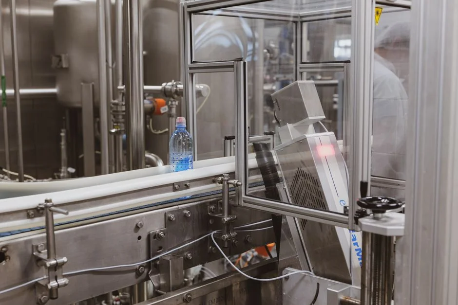
Phase 2 locks the unit processes, the hydraulic profile, and the equipment list. It is where the project decides whether it is a package/skid build or a custom EPC build, and where disinfection and clarification choices are committed to drawings. This phase must finish before procurement issues any long-lead purchase order.
Engineering deliverables are a P&ID, mass balance, hydraulic profile, equipment list with duty points, and general arrangement drawings. These sit ahead of civil, structural, and E&I detailed design — a sequencing rule that is routinely broken on fast-track projects and almost always produces rework. The first big decision is package versus custom: a skid-mounted underground package sewage treatment plant suits low-to-mid flows with a stable influent, while a custom EPC build is the right answer for larger or highly variable industrial loads, or where discharge limits require tight biological control.
Two unit-process decisions drive most of the downstream cost. Clarification: a dissolved air flotation system is the correct first choice for high FOG or colloidal loads, where its hydraulic loading range and sludge blanket capture outperform settling; lamella clarification suits lower-colloidal streams and reduces chemical consumption. Disinfection: a chlorine dioxide generator provides residual disinfection across a wide output range with documented compliance against EPA, EU 98/83/EC, and WHO requirements; a UV sterilizer for water treatment is chemical-free and is the better fit where chlorine-resistant organisms such as Cryptosporidium and Giardia are the governing target. For flows above package-plant scale, the MBR membrane bioreactor system consolidates biological treatment and solids separation in a single tank, simplifying hydraulic profile and improving effluent quality.
| Decision | Choose When | Equipment Reference |
|---|---|---|
| Package / skid plant | Stable influent, low-to-mid flow, fast delivery | WSZ underground unit |
| Custom EPC build | Variable industrial load, tight consent, future expansion | MBR + DAF + ClO₂ train |
| DAF clarification | High FOG or colloidal fraction | Dissolved air flotation unit |
| Lamella clarification | Lower colloidal load, chemical minimisation priority | Lamella plate pack |
| ClO₂ disinfection | Residual required, broad pathogen target | Chlorine dioxide generator |
| UV disinfection | Chlorine-resistant pathogens, no chemical residual wanted | UV sterilizer |
For the broader trade-off between biological routes, the aerobic vs anaerobic wastewater treatment decision framework walks through the duty and energy logic. Regional cost benchmarks are covered in the effluent treatment plant buyer's guide with costs and compliance.
Phase 3: Procurement and Fabrication
Procurement has to start before the engineering drawings are 100% sealed, because long-lead items will eat the float if they are ordered after IFC. The rule is: purchase against approved-for-design data sheets, then release the final order the moment IFC drawings are sealed.
Long-lead items on a typical water treatment plant are UF and MBR membrane modules, RO skids, multi-media filters, and large chlorine dioxide generators. Their delivery windows routinely run longer than the construction programme, so the procurement schedule must be visible in the master EPC schedule from day one of Phase 2. When evaluating membrane or sorbent suppliers, ask for the kind of mechanical and QC data a serious vendor publishes: the 2026 J Sep Sci Gemini-cellulose paper (Vol. 49(9), Sep 2026) reported dry tensile strength of 25.16 MPa and wet tensile strength of 1.54 KN/m with a 0.29 wet-strength ratio — concrete numbers a buyer can use as a benchmark when comparing paper-, membrane-, or sorbent-based products.
Packaging matters for export. Equipment should be crated to ISO 1496 with seaworthy bracing, desiccants, and humidity control for electrical panels; control cabinets and VFDs in particular must arrive within their storage humidity specification or the warranty clock starts against you before installation. Outputs of Phase 3 are approved vendor data sheets, agreed inspection and test plans (ITPs), and a delivery schedule locked against the construction programme — for membrane and filter consumables, see the RO and UF membrane filter elements range.
Phase 4: Civil and Mechanical Construction
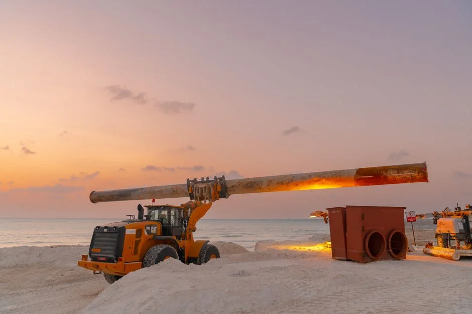
Construction is where most project managers feel comfortable, because the work is visible. It is also where the schedule most often hides future commissioning risk, because the work is split across three contracting parties that must be coordinated by a named role.
Scope split is contractual: civil (tanks, foundations, pipe racks, building shells) is the general contractor; mechanical (piping, equipment erection, alignment) is the process contractor; electrical and instrumentation is a specialist subcontractor. Without a named construction coordinator, the interfaces between these three will leak — cable trays land on pipe racks, instrument locations miss the equipment, and the punch list at mechanical completion is longer than the construction window.
Safety sign-off is a hold point, not a formality. Confined-space entry, hot work, and lifting plans must be approved per OSHA or local equivalent before any tank entry; skip this and the schedule pays it back during commissioning. Construction quality is also a hydraulic issue: tank baffling, weir levels, and launder slopes must be built to design tolerance, because a clarifier or DAF that is 20 mm off design will not perform at the duty the performance test will demand. The mid-phase hold point is the mechanical completion certificate, the walk-down punch list, and the pre-commissioning cleaning plan — flushing, blowing, and chemical rinse of RO and UF lines — all signed before water-on begins.
Phase 5: Commissioning and Performance Testing
Commissioning is the phase that top-ranking pages treat as a single event. In practice it is three staged gates that must be passed in order, and the gap between mechanical completion and water-on is the single biggest source of project slippage on industrial water treatment builds.
The three stages are: pre-commissioning, with no water, where instrument loops are checked, motors are bump-tested, and safety interlocks are proven; commissioning, where water is introduced and individual equipment is run under no-load and then design-load conditions; and the performance test, typically 7–30 days on design influent, which is the contractual demonstration that the plant meets its duty. Performance is judged against the consent: for the EU market, against UWWTD 91/271/EEC discharge criteria; for US industrial pretreatment, against the local POTW's 40 CFR-driven limits; for potable reuse, against EU 98/83/EC or the WHO Guidelines for Drinking-water Quality.
Membrane systems need their own ramp-up discipline: flux stepping on a controlled schedule, clean-in-place sequence validated, and integrity testing for UF or MBR pore sizes in the 0.03–0.1 µm range with filtrate turbidity held below 1 µm per the MBR data sheet. Sludge handling must be specified by then — a plate and frame filter press for batch dewatering duty, paired with an automatic chemical dosing system for conditioning polymer, is the common selection. Outputs of Phase 5 are the performance test report, as-built drawings, O&M manuals, and training records — together, the O&M handover package.
Phase 6: Operations Handover and Training

Phase 6 is the one that buyers most often forget to schedule, and the one that determines whether the plant runs well for the next 20 years or starts drifting within the first 12 months. The plant is "complete" on paper, but operations are not yet ready to run it.
The handover pack must include as-built drawings, O&M manuals, a spare parts list with lead times, the warranty schedule, and the SCADA and PLC source code with the password register. Training needs both a classroom component on process theory and hands-on time on the actual installed equipment — operators must be able to respond to a power failure, a chemical spill, and a membrane CIP alarm without phoning the EPC for help. Establish a performance baseline at handover so future deviations are measurable, then review at 30, 90, and 365 days.
A common gap is that the first sludge dewatering cycle is not planned. Specify the plate and frame filter press or belt press selection during design — not after handover — and make sure the polymer dosing system and cake handling are sized for the duty. For control system handover, the SCADA system engineering guide for industrial wastewater plants sets out the documentation, tag naming, and cybersecurity handover points that an owner typically needs to lock at this stage.
Frequently Asked Questions
How much does it cost to build a water treatment plant in 2026?
No single published 2026 figure covers the full range of industrial and municipal duty. Cost depends on influent quality, flow, discharge consent, and whether the build is a package skid or a custom EPC. The defensible input for a budget is a Class V estimate built off a basis-of-design report (Phase 1) and at least three vendor quotations on long-lead items (Phase 3); without those, any number quoted up front is a placeholder. Buyers should ask EPC bidders for a cost breakdown by WBS code and by phase, not a single lump sum.
How do I choose between a package plant and a custom EPC build?
Package plants win on delivery speed and capex predictability for stable, low-to-mid flow influents where the consent is not unusually tight. Custom EPC builds are the right answer for variable industrial loads, future expansion, or discharge limits that demand tight biological control. The decision point in the engineering schedule is Phase 2, after the treatability data is in hand — never before.
What is the difference between mechanical completion and water-on commissioning?
Mechanical completion means equipment is installed, aligned, and loop-checked dry, with the punch list signed and pre-commissioning cleaning complete. Water-on commissioning means the plant is running on real influent for the first time, individual units are started under load, and the biological system is seeded and ramped. Most industrial project slippage occurs in the gap between these two milestones, so schedule float should be assigned there, not on the construction months.
Which regulations apply to my plant in 2026?
It depends on what the plant discharges to. For municipal and medical discharges in the EU, the Urban Waste Water Directive 91/271/EEC sets the discharge criteria. For potable reuse projects, the Drinking Water Directive 98/83/EC and the WHO Guidelines for Drinking-water Quality apply. In the US, industrial pretreatment is governed by 40 CFR Part 430 for pulp and paper and by the local POTW's 40 CFR-driven discharge limits for other sectors. The consent letter from the regulator is the controlling document — confirm it before the basis-of-design report is signed.