Why a Kolkata Fab or Data Hall Cannot Run a Copied Design Basis in 2026
A 2026 semiconductor fab or hyperscale data hall in the Kolkata metropolitan area cannot be designed against a sea-level, Andean, or Hsinchu reference; the binding instrument is West Bengal Pollution Control Board (WBPCB) consent to establish and consent to operate under the Water Act, 1974 and the Air Act, 1981, framed by CPCB industry-specific effluent standards, and the Ganga-basin location puts the site inside the global water-disruption risk curves.
TNFD 2026 reports that 45% of global data centres sit in basins at high water-disruption risk, and Lepawsky (2024) projects that more than 40% of new fabs will be in high or extremely high water-stress basins by 2030, so a Bengal site in the lower Ganga catchment inherits both risk categories. A single fab draws around 14 billion litres of UPW per year — equivalent to a city of 7.5 million people (TNFD 2026, citing WEF 2025 and S&P Global 2024), and the 1.4–1.6 m³ feed per 1 m³ UPW ratio published by IDE Technologies in 2024 means a 4,000 m³/day fab draws 5,600–6,400 m³/day before any recycle — a number the finance committee will read carefully. WBPCB consent, not Resolución 631/2015 or a CAR Cundinamarca permiso de vertimientos, is the binding 2026 instrument, and foreign Resoluciones must be replaced with Indian citations in the EIA chapter. Kolkata's pre-monsoon wet-bulb swing, not the 10–14 °C annual mean cited for Bogotá, sets the cooling-tower cycles and the DAF saturator re-rate, and the derate is climate-specific, not the 10–12% per 1,000 m altitude penalty from the Bogotá guide.
Three Segregated Wastewater Streams Every Kolkata Site Must Carry
Stream segregation at the headworks is the single biggest design decision for any Kolkata fab or hyperscale data hall, and the cost of getting it wrong is an MBR biomass kill from a fluoride shock or a blinded RO pre-filter set from co-mingled CMP slurry. The defensible 2026 baseline carries three segregated feed lines through the train, and a data hall without fab cleaning collapses to Streams 1 and 3 only, with blowdown TDS at 1,200–6,000 mg/L on the Hooghly and deeper Ganga-basin source water (Genesis Water Technologies, 2026). Stream 1 — UPW reject and general rinse — is the largest by volume, low in TDS and TSS, near-neutral pH, and routes through equalisation, multi-media filtration, and an RO pass (or 2-pass for UPW reclaim). Stream 2 — the chemical-bearing line — carries CMP slurry with colloidal silica or ceria and surfactants, HF and NH4F rinses, IPA, acid and caustic cleaning baths, and photoresist developer waste; ScienceDirect 2023 (S3) confirms fluoride, TMAH-developer, ammonia and phosphate as the headline fab contaminants, with high fluoride, COD spikes of 500–2,000 mg/L, colloidal silica and FOG defining the duty. Stream 3 — cooling-tower and boiler blowdown plus a small scrubber-liquor sidestream from acid-gas abatement — is high in TDS, silica and residual scale inhibitors, with low-pH spikes from acid-gas abatement. Two buffer tanks, each sized for ≥8 hours at peak instantaneous flow, are the minimum headworks on the chemical and cooling-tower feed lines, paired with a rotary mechanical bar screen on each chemical and cooling-tower feed line; the long equalisation window is the engineering response to the opaque, proprietary fab wastewater composition flagged by the ScienceDirect 2025 review (S5). Segregation at the headworks is not optional: fluoride shocks will poison MBR biomass, and CMP slurry will blind the RO pre-filter within hours if the streams co-mingle.
| Stream | Sources | Headline chemistry | Headworks |
|---|---|---|---|
| 1 — UPW reject / general rinse | UPW polishing loop bleed, wafer rinses | Low TDS (<50 mg/L), low TSS, near-neutral pH | Equalisation → MMF → RO (2-pass for UPW reclaim) |
| 2 — Chemical / CMP / fluoride / IPA | CMP slurry, HF/NH4F rinses, acid/caustic baths, photoresist developer | High F, COD spikes 500–2,000 mg/L, colloidal silica, FOG | Equalisation → DAF → MBR → RO; concentrate manifest as hazardous |
| 3 — Cooling-tower + boiler blowdown, scrubber liquor | Tower blowdown, boiler blowdown, acid-gas scrubber | TDS 1,200–6,000 mg/L, silica, scale inhibitors, low-pH spikes | Equalisation → side-stream MMF → UF → RO (50–70% local recovery) |
The Six-Step Treatment Train Sized for 1,000–6,400 m³/day
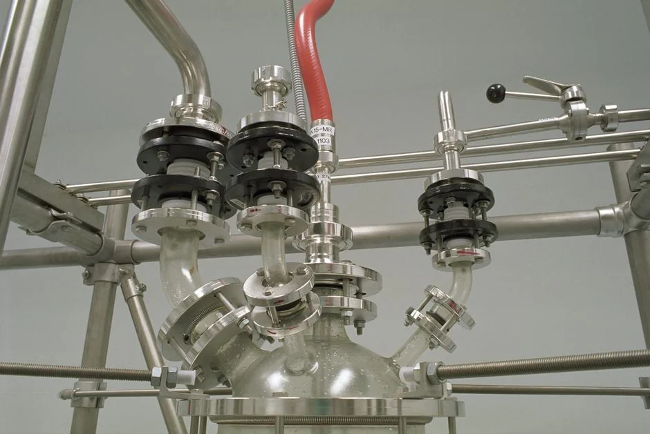
The defensible 2026 train is a six-step chain sized for the 1,000–6,400 m³/day envelope that covers a 5–20 MW data hall or a mid-scale fab on the Hooghly and deeper Ganga-basin source water. Step 1 — Equalisation: two buffer tanks ≥8 h at peak flow with three segregated feed lines, plus a rotary mechanical bar screen on the chemical and cooling-tower feed lines, mandatory for grid-event resilience and for absorbing the opaque feed spikes noted in S5. Step 2 — Pretreatment: a DAF unit for CMP and oily streams (2 duty + 1 standby, with the saturator re-rated for site-specific air density rather than the 0.74 atm Bogotá number); a lamella clarifier for high-TSS batch spikes; a multi-media filter to SDI <5 ahead of the RO, because the IDE MAXH2O case explicitly flagged SDI persistently above 5 as the dominant failure trigger of a conventional RO on a fab feed. Step 3 — Biological: a submerged PVDF MBR cassette with a 0.1 µm pore size at 32–135 m³/day per 80–225 m² cassette, with the blower sized for the local OTE penalty; the 60% smaller footprint versus activated sludge is the standard claim, and footprint compression matters when a Bengal site is competing for land cost in the Salt Lake / Rajarhat corridor. Step 4 — Two-pass RO with energy recovery: a two-pass industrial RO with energy recovery anchored on the IDE MAXH2O benchmark of ~720 GPM (~4,000 m³/day) at 54% first-pass recovery (silica-limited), climbing to 88% total when the upstream brine is sent through a second pass; include a boron-rejection option if the recovered water is feeding a fab UPW reclaim loop. Step 5 — Polishing: an EDI or mixed-bed for fab UPW reclaim, a UV unit at 40 mJ/cm² on the RO permeate line for data-hall cooling-tower reuse loops, and a ClO₂ generator for residual control in long distribution lines. Step 6 — Reuse allocation: 60–80% of the treated stream to cooling-tower make-up, scrubber make-up and toilet flushing, with the remaining 20–40% discharged to the municipal sewer or a Hooghly-adjacent surface water body under WBPCB consent. For context on the global envelope, the global chip-fab ZLD blueprint walks the same six-step logic at design basis.
| Step | Equipment / sizing rule | Design basis note |
|---|---|---|
| 1 — Equalisation | ≥8 h at peak flow, three segregated lines, rotary mechanical bar screen | Mandatory for grid-event resilience |
| 2 — Pretreatment | SDI <5 to RO; 2 duty + 1 standby DAF; lamella for TSS spikes | Re-rate DAF saturator for local air density |
| 3 — Biological | 0.1 µm PVDF, 32–135 m³/day per 80–225 m² cassette | Oversize blower for local OTE penalty |
| 4 — Two-pass RO | ~720 GPM, 54% pass 1, 88% total; energy recovery; boron option | Derate specific flux 10–20% per pilot |
| 5 — Polishing | 40 mJ/cm² UV; ClO₂ for long lines; EDI for fab UPW reclaim | UV for data-hall loops, EDI for fab reclaim |
| 6 — Reuse allocation | 60–80% reuse, 20–40% discharge | Cite CPCB reuse reporting frame, not Resolución 1207/2014 |
Choosing Between Partial Reuse, High-Recovery CTBD and Full ZLD
Partial reuse at 60–85% overall recovery is the 2026 default for 5–20 MW Bengal sites, and it is the configuration WBPCB and the local utility will usually accept when a multi-year discharge consent is asked for. High-recovery cooling-tower blowdown (CTBD) with controlled salt precipitation at ~95% recovery and ~1 mg/L silica permeate is the right upgrade for sites near the Ganga recharge zone or the East Kolkata Wetlands where concentrate disposal is restricted (IDE Water, 2026 framing). Full ZLD — RO + MVC + crystallizer — reaches 95–99% overall recovery but only pencils at 20 MW, with $3–8M CAPEX and $5–15/kgal OPEX (Genesis Water Technologies, 2026); it should be reserved for sites where WBPCB refuses concentrate discharge or where pre-monsoon freshwater rationing is the binding constraint, not the default for sub-20 MW sites. Discharge-only is a stopgap: WBPCB TDS caps and direct discharge fees erode the savings within a year, so a 5–20 MW site that starts as discharge-only should be planned from day one to add a side-stream UF + RO module in 1–2 MW increments as the hall fills over 18–24 months, drawing on RO and UF membrane elements phased with the load. For the cooling-tower make-up line, the multi-media filter ahead of the side-stream RO protects the membrane train from silt-density excursions during the monsoon.
| Site driver | End-of-pipe configuration | Why this fits |
|---|---|---|
| Sewer has headroom, TDS <1,500 mg/L achievable | Partial reuse (side-stream + UF + RO) | WBPCB default, multi-year consent |
| Pre-monsoon freshwater rationing | High-recovery CTBD (controlled salt precipitation) | ~95% recovery, ~1 mg/L silica permeate |
| Permit restricts concentrate discharge | Full ZLD (RO + MVC + crystallizer) | 95–99% overall recovery, ~20 MW break-even |
| 5–20 MW, sub-breakeven, phased build | Discharge-only → side-stream + UF + RO retrofitted in 1–2 MW steps | Phased over 18–24 months as hall fills |
Screening-Grade CAPEX and OPEX for a 5, 10 and 20 MW Kolkata Site
The screening-grade bands below are translated from the Bogotá 2026 reference (Genesis Water Technologies, 2026) and must be re-cut for BCD, IGST, West Bengal VAT/GST, monsoon-driven wet-bulb derating, and Ganga-basin seismic and wind derating before they are carried into an EPC tender; the figures are not a quotation. A 5 MW Kolkata site on 1,000–1,500 m³/day makeup (250–450 m³/day blowdown) lands at $0.4–0.9M CAPEX and $1.50–3.00/kgal OPEX for a side-stream + UF + RO train at 50–70% local recovery. A 10 MW site roughly doubles the train to $0.8–1.6M CAPEX, with OPEX in the same per-kgal band because fixed costs dilute across more volume. A 20 MW site is where ZLD becomes a real option: $3–8M CAPEX and $5–15/kgal OPEX, justified only when concentrate discharge is refused and freshwater is curtailed. For an Indian reader translating to a board memo, the conversion band at 2026 reference rates puts a 5 MW site in roughly the low single-digit ₹ Crore range for a partial-reuse train, a 10 MW site at low-to-mid single-digit ₹ Crore, and a 20 MW ZLD site from low double-digit ₹ Crore upward, with the same wide range driven by membrane selection, seismic derate, and BCD/IGST exposure on imported skids; the engineering buyer should request vendor quotations indexed to the Kolkata source water and Indian seismic zone rather than rely on the translated band alone. The 60–85% partial reuse framing is higher-value than ZLD for sub-20 MW sites, and the sustainability committee will usually accept that case more easily than a ZLD retrofit that pencils only at the upper end of the size band. For a peer benchmark on equipment cost spreads, the CMP wastewater equipment cost comparison walks the line-item level.
| Site size | Daily envelope | Train | CAPEX band (USD) | OPEX band |
|---|---|---|---|---|
| 5 MW | 1,000–1,500 m³/day (250–450 blowdown) | Side-stream + UF + RO, 50–70% local recovery | $0.4–0.9M | $1.50–3.00/kgal |
| 10 MW | ~2,000–3,000 m³/day | Side-stream + UF + RO, phased skids | $0.8–1.6M | $1.50–3.00/kgal |
| 20 MW | ~4,000–6,000 m³/day | Side-stream + UF + RO + MVC + crystallizer (ZLD) | $3–8M | $5–15/kgal |
Procurement Short-List and the On-Site Pilot That Has to Precede It
The procurement short-list maps each unit operation to a specific equipment class and sizing rule so the engineer can request quotes against a defensible envelope. Headworks: rotary mechanical bar screen on chemical and cooling-tower feed lines. Flotation: DAF units at 4–300 m³/h, 2 duty + 1 standby for grid-event resilience. Biological: DF-series submerged MBR cassettes, 0.1 µm PVDF at 32–135 m³/day per 80–225 m² cassette, with the blower sized for the local OTE penalty. RO: two-pass industrial RO with energy recovery, CIP skids and a boron-rejection option for semiconductor-grade reuse, paired with an automatic chemical dosing system for PLC-controlled antiscalant and pH control. Disinfection and sludge: UV primary for cooling-tower reuse loops; ClO₂ generator for long distribution lines; a plate-and-frame filter press for MBR WAS, with the cake manifested under the CPCB hazardous-waste rules, not a foreign Resoluciones frame. Source RO and UF membrane elements as a single lot so cleaning chemistry is consistent across stages, and pair every RO with a PLC-controlled antiscalant and pH dosing skid. Lock all sizing behind a 1–3 month on-site pilot at the actual Hooghly / deeper Ganga source water; this is the engineering response to the opacity flagged by S5 and the only defensible basis for derating vendor flux and recovery curves before procurement. For the MBR cassette lifecycle, the MBR O&M engineering manual is the right reference document, and any PFAS filtration for fab runoff should be characterised during piloting, not deferred to commissioning.
Frequently Asked Questions
What is the realistic 2026 cost band for a Kolkata fab or hyperscale data hall wastewater train in ₹ Crore?
For a 5 MW Kolkata site on 1,000–1,500 m³/day makeup, the partial-reuse train (side-stream + UF + RO at 50–70% local recovery) lands in the low single-digit ₹ Crore range after translating the $0.4–0.9M CAPEX and $1.50–3.00/kgal OPEX bands (Genesis Water Technologies, 2026); a 10 MW site roughly doubles that to the low-to-mid single-digit ₹ Crore range, and a 20 MW ZLD site runs from low double-digit ₹ Crore upward on the $3–8M CAPEX band. These are screening-grade numbers, not EPC tender prices — the buyer must add BCD, IGST, West Bengal VAT/GST, monsoon wet-bulb derating, and Ganga-basin seismic and wind derating before the figure can be defended to a finance committee.
How should a buyer short-list suppliers for a Kolkata semiconductor or data hall wastewater project?
The defensible supplier-selection filter is the on-site pilot and the single-lot membrane procurement rule: the vendor must commit to a 1–3 month on-site pilot at the actual Hooghly or deeper Ganga source water before sizing is locked, and RO and UF membrane elements should be sourced as a single lot so cleaning chemistry is consistent across stages. Pair every RO with a PLC-controlled antiscalant and pH dosing skid in the same package, and confirm the MBR blower is re-rated for the local OTE penalty rather than a sea-level reference curve.
How long does the WBPCB consent process take, and how does it interact with the water intake permission?
WBPCB consent to establish and consent to operate under the Water Act, 1974 and the Air Act, 1981 must be cleared in parallel with the intake / drawl permission, because CPCB industry-specific effluent standards frame the discharge envelope that the intake volume has to balance. The source research flags the parallel-permit logic without naming a Bengal-specific month count, so the buyer should request a current WBPCB processing-time letter at the pre-tender stage rather than assume a global timeline.
How long should the on-site pilot run before the EPC tender is floated?
The pilot should run 1–3 months on the actual Hooghly or deeper Ganga source water so that the Indian monsoon wet-bulb swing is captured in the flux and recovery data; a shorter pilot under-samples the pre-monsoon to monsoon transition and is not defensible to a sustainability committee or a board memo. The pilot is the engineering response to the opaque, proprietary fab wastewater composition flagged in the ScienceDirect 2025 review (S5), and it is the only defensible basis for derating vendor flux and recovery curves before procurement.