
Why the Ashland Petroleum Wastewater Question Matters in 2026
The Marine River Terminal in Catlettsburg, Kentucky — immediately adjacent to Ashland across the Big Sandy River — is the most documented petroleum wastewater failure case in this watershed. Barge-dewatering wastewater there carried solids, oil and grease, BTEX, metals, BOD, and occasional arsenic. An equalisation tank plus DAF unit installed before 2001 could not meet the City of Ashland POTW discharge criteria, and an MBR retrofit was commissioned in 2002 to bring the site into compliance (Digital Refining, 2025). That case is the spine of this guide: a primary-separator failure on a real Ashland-adjacent petroleum stream, with documented influent character and removal performance.
For a 2026 capital project, the question is sharper than it was in 2001. Tighter effluent expectations, growing water-reuse pressure inside the BMRTP and Ohio River watershed, and rising hauling fees for wet sludge have turned the DAF-or-clarifier decision into a 10-year compliance and OPEX commitment. The scope of this article is narrow: the primary oil/water separation step only, with biological polishing assumed downstream.
What Petroleum Wastewater in Ashland Actually Contains
Petroleum wastewater is a four-fraction mixture, and each fraction responds to a different unit operation. Free oil (specific gravity <0.9) floats and is easily captured by an API separator or a DAF skimmer, but a conventional clarifier cannot lift it — gravity settling pushes it the wrong way. Emulsified oil and FOG sit near 1.0 specific gravity; they will not settle under any plausible clarifier retention time, and they will float only when micro-bubbles attach to flocculated droplets — which is exactly what a DAF does.
BTEX compounds (benzene, toluene, ethylbenzene, xylene) and trace metals are dissolved or finely suspended. Neither DAF nor a clarifier removes them at meaningful rates; they must be biodegraded or adsorbed. The Marine River Terminal retrofit measured greater than 98% BTEX removal, and that work was performed by the MBR, not by the upstream DAF (Digital Refining, 2025). Dissolved salts and high COD from refinery desalter brine are the same problem in a different wrapper — non-settleable, non-floatable without chemistry, and a load that biological polishing must carry downstream.
How a DAF Clarifier Works on Oily Wastewater
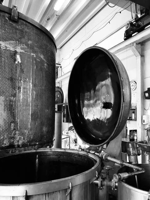
A DAF is a four-stage engineered sequence: coagulation/flocculation, air dissolution, bubble–particle attachment, and flotation/skimming. Coagulant and polymer are dosed upstream to bridge oil droplets and fine solids into buoyant flocs. A side-stream recycle — typically 10–30% of clarified effluent — is pressurised to 4–6 bar in an air-saturation vessel, then released to the flotation tank through needle valves or nozzles. The pressure drop nucleates a cloud of 20–100 μm micro-bubbles that attach to the flocs and lift them to the surface, where a skimmer sweeps the float into a trough.
Operating parameters dictate performance on petroleum streams. Polymer dose is 0.5–5 mg/L, pH window 6.5–8.5 for floc strength, and an automatic chemical dosing system is recommended for streams that slug-load, which includes most refinery and terminal wastewater. Typical performance: 92–97% TSS removal, free oil skimmed upstream in an API or coalescer, and emulsified oil cut to below 5 mg/L when DAF is paired with a nutshell or coalescing polisher — the configuration used at the São José dos Campos refinery train (Digital Refining, 2025). The right hardware for this duty is a DAF system rated to the design flow with stainless construction matched to chloride exposure.
Why a Conventional Clarifier Struggles with Petroleum Streams
A clarifier is a passive vessel that works when the contaminant is denser than water and the residence time is long enough for Stokes' law to apply. Petroleum wastewater presents the opposite problem. Free oil, emulsified oil, and FOG are lighter than or nearly equal to water, so the clarifier's only tools are chemical — coagulants and polymers dosed heavily enough to drag oil droplets down with the sludge. That works poorly, inflates OPEX, and produces wet underflow at 1–2% solids that is expensive to haul (HydropureWater, 2025).
Beyond chemistry, the retention time itself is the constraint. Effective sedimentation needs 2–4 hours, which means a 50 m³/h clarifier needs a basin on the order of 100–200 m³ — roughly 4–5× the footprint of a DAF doing the same job. On the cramped barge terminals and small refinery sites common around Ashland, that footprint alone can make the clarifier option impractical.
DAF vs Clarifier for Petroleum Wastewater: Head-to-Head Comparison
The table below condenses the engineering trade-off into a single artifact for project planning. Every value is drawn from field data on DAFs (HydropureWater, 2025) and from the documented Marine River Terminal and São José dos Campos refinery trains (Digital Refining, 2025).
| Parameter | Dissolved Air Flotation (DAF) | Conventional Clarifier |
|---|---|---|
| Oil & grease removal | Up to ~95% FOG; emulsified oil <5 mg/L with nutshell polish | Poor; relies on overdosed coagulants to drag oil down with sludge |
| TSS removal | 92–97% | 50–70% on light/organic streams; better on heavy inorganics |
| Surface loading rate | 5–15 m/h | ~1–2 m/h |
| Footprint at 50 m³/h | ~20–25% of clarifier footprint | 4–5× larger than DAF |
| Sludge solids | 3–5% float (cake to 25–35% with filter press) | 1–2% underflow |
| Energy | 0.2–0.5 kWh/m³ | Near zero mechanical, offset by higher chemical use |
| Chemical demand | 0.5–5 mg/L polymer, controlled | Often heavy coagulant overdose to force FOG settling |
| CAPEX class (50 m³/h) | ~$50,000–$500,000 (SS304/SS316, automation) | Lower vessel cost, higher civil/land cost |
| OPEX drivers | Energy, polymer, sludge hauling | Polymer/coagulant, sludge hauling (2–3× volume) |
| Sensitivity to slug loads | Recycle ratio and pressure can be tuned to absorb shocks | Spills upset clarifier blanket; recovery is slow |
| Best downstream partner | Nutshell filter → MBR or activated sludge | Rarely used as sole primary on petroleum streams |
DAF outperforms the clarifier on every petroleum-relevant metric — oil and grease, FOG, emulsified contaminants, footprint, and sludge dryness — often by 3–5×. A clarifier is competitive only on streams dominated by heavy inorganic solids (grit, sand, metal shavings) with minimal oil, which does not describe Ashland petroleum streams.
2026 Decision Framework: When to Pick DAF, Clarifier, or Both
For an Ashland petroleum site in 2026, the default train is API oil/water separator → DAF → biological polish (MBR or conventional activated sludge). The API separator provides insurance against free-oil shock loads, the DAF captures the emulsified oil and FOG that the API cannot, and the biological step removes BTEX and dissolved COD.
A conventional clarifier earns a place in two specific roles. First, as a polishing step after a DAF, where a quiescent basin helps settle any residual floc carryover. Second, it should not be used as the sole oil-removal unit on petroleum wastewater, as heavy slug loads and emulsified oil will defeat it.
Two refinements are worth specifying into the 2026 design. Add a nutshell or coalescing filter between the DAF and the MBR membrane bioreactor to keep oil carryover below 5 mg/L — the configuration used at the São José dos Campos refinery (Digital Refining, 2025) — and protect the membranes from oil fouling. Add automated polymer and pH control through an automatic chemical dosing system so floc strength holds during crude-quality swings, which push more metals, solids, and tramp amines from the desalter into the brine (Digital Refining, 2025).
Worked Example: 50 m³/h Petroleum Wastewater Plant in Ashland
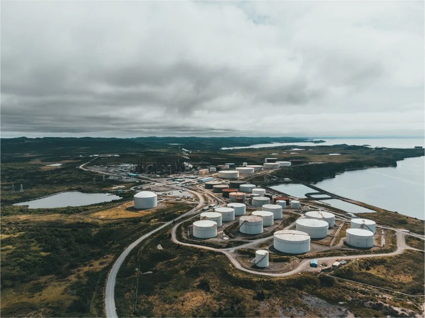
A 50 m³/h mixed petroleum wastewater stream is typical for a small refinery, terminal, or barge operation in the Ashland area. Design case: free oil removed by an API separator, emulsified oil and FOG polished by a DAF, BTEX and dissolved COD handled by an MBR. DAF sizing maps to a DAF system at 50 m³/h; CAPEX lands between $50,000 and $500,000 depending on SS304 versus SS316 construction and automation level (HydropureWater, 2025).
Operating costs include energy at 0.2–0.5 kWh/m³ (about 25 kW continuous load) and polymer at 0.5–5 mg/L. Sludge volume is 50–70% lower than an equivalent clarifier, which projects to significant annual savings in avoided hauling fees (HydropureWater, 2025). Upstream of the DAF, a rotary mechanical bar screen protects the recycle pump and air-injection nozzles from debris. Downstream, a plate-and-frame filter press dewaters the float to 25–35% solids for cheaper off-site disposal.
Compared to a clarifier-only scheme on the same 50 m³/h, the clarifier requires a footprint 4–5× larger, generates 2–3× the sludge volume, and fails to meet emulsified-oil limits without heavy coagulant dosing. Civil work and land requirements often close the CAPEX gap before OPEX is even calculated.
Operational Best Practices for DAF on Petroleum Streams
Four habits separate a DAF that performs from one that drifts into non-compliance. First, pre-screen with a rotary bar screen at 2–6 mm aperture so debris does not foul the recycle pump or air-injection nozzles. Second, hold the air-saturation vessel inside the 4–6 bar window and keep the recycle ratio between 10% and 30% — too low and there are not enough bubbles to lift the float; too high and the turbulence shears the flocs (HydropureWater, 2025).
Third, run monthly jar tests on the actual wastewater to confirm polymer charge and dose, and hold pH between 6.5 and 8.5 so flocs are strong enough to ride the bubbles without breaking. Fourth, send the float to a plate-and-frame filter press so dewatered cake reaches 25–35% solids; that single change typically cuts annual hauling cost by half on a 50 m³/h stream. For plants comparing biological polishers downstream, the MBR vs conventional activated sludge ROI comparison lays out the trade-off, and the MBR troubleshooting guide covers the failure modes inherited if DAF carryover is not controlled upstream.
Frequently Asked Questions
Is a DAF or a clarifier better for petroleum wastewater in Ashland?
A DAF is the better primary separator on petroleum wastewater. It hits 92–97% TSS removal, cuts emulsified oil below 5 mg/L when paired with a nutshell polisher, and operates at 5–15 m/h surface loading versus 1–2 m/h for a clarifier — roughly 4–5× the footprint saving (HydropureWater, 2
Frequently Asked Questions
DAF or clarifier for petroleum wastewater — which is better?
The choice depends on the specific gravity of the suspended solids and oil droplets. DAF (Dissolved Air Flotation) is generally superior for petroleum wastewater because it excels at removing particles with a specific gravity near or less than 1.0, such as free-floating oils and grease. Clarifiers rely on gravity sedimentation and are more effective for dense, inorganic solids that settle rapidly.
Can a clarifier remove emulsified oil from refinery wastewater?
No, a standard clarifier cannot effectively remove emulsified oil. Emulsified oil droplets are typically smaller than 20 microns and possess surface charges that prevent them from settling by gravity. Removing these requires chemical de-emulsification or DAF systems that utilize micro-bubbles to attach to the droplets and force them to the surface.
How much oil and grease can a DAF remove in petroleum wastewater?
A properly operated DAF unit can achieve oil and grease removal efficiencies ranging from 80% to 95%. When integrated with appropriate chemical coagulation and flocculation, effluent oil and grease concentrations can frequently be reduced to levels below 50 mg/L, depending on the influent loading and bubble-to-particle ratio.
What is the footprint difference between a DAF and a clarifier?
DAF systems have a significantly smaller footprint than clarifiers, often requiring 70% to 80% less surface area for the same hydraulic loading rate. Because DAF units utilize air-induced buoyancy rather than gravity settling, they can operate at rise rates of 2 to 4 gallons per minute per square foot, compared to 0.5 to 1.0 gallons per minute per square foot for typical primary clarifiers.
Does a DAF meet City of Ashland POTW discharge limits for petroleum sites?
A DAF unit is often a necessary component to meet City of Ashland POTW discharge limits, particularly for Total Petroleum Hydrocarbons (TPH) and Oil & Grease (O&G). While local discharge permits vary, most municipal sewer use ordinances require O&G concentrations to remain below 100 mg/L to prevent line blockages and interference with biological treatment processes; a DAF system is typically the primary technology used to ensure compliance with these specific pretreatment standards.