Why Marseille Is a Water-Specific Data Center Site
Interxion's roughly €400M investment in Marseille placed the city 9th globally among Internet hubs, and the €15M River Cooling capex co-developed with Dalkia Smart Building (an EDF subsidiary), backed by ADEME and Région Sud, turned that capital into the lowest-energy hyperscale sites in France (S5). The reason is La Galerie de la Mer, an 1885–1907 mining-drainage tunnel originally built to evacuate infiltration water from the former Mines de Gardanne, which still discharges legacy mine water into the Mediterranean at ~15°C year-round. River Cooling pipes that gallery water into plate heat exchangers at MRS2, MRS3 and the upcoming MRS4, where it directly absorbs server heat without running chillers (S2, S5). The result is a measured PUE of 1.11, against a 1.38 average for traditional liquid-cooled data centers, saving 18,400,000 kWh/yr and avoiding 795 t CO2/yr, with free-cooling covering 100% of the load 98.9% of the time after maintenance (S2).
That asset is what makes Marseille buildable at all, but it also creates a treatment duty the operator cannot outsource. The gallery water must be filtered before plate exchangers and chillers, the closed chilled-water loop concentrates silica, calcium carbonate and calcium sulfate into a cooling-tower blowdown (CTBD) stream that cannot be sent to a municipal sewer, the on-site population generates sanitary wastewater subject to EU collection rules, and roughly 40% of facility energy still touches the chilled-water system, so any water-chemistry slip directly shows up on the PUE meter (S5). Engineers scoping the site for similar free-cooling context should review the Alexandria data center blowdown treatment guide for a Mediterranean-twin reference case, and the Quito data center blowdown treatment guide for a contrasting high-altitude baseline.
Marseille Water Balance: What Comes In, What Goes Out
A 100 MW hyperscale site in the MRS3/MRS4 class can draw up to 2 million L/day from its gallery intake plus auxiliary sources (S1). For the Marseille profile, three intake streams converge on the site: La Galerie de la Mer gallery water for direct heat exchange, fresh make-up for the closed chilled-water and cooling-tower loop, and potable water for domestic use (S1, S2). On the outlet side, the facility generates four distinct waste streams, each with its own treatment duty: cooling-tower blowdown enriched in silica, CaCO3 and CaSO4; backwash from the gallery-water multimedia filters; site sanitary wastewater from staff and visitors; and, once the Euroméditerranée heat-export loop is live, condensate leaving the secondary district-heating interface (S1, S2, S5).
The volumetric signal is clear. At typical cycles of concentration (CoC) of 4, cooling-tower blowdown equals 25% of make-up volume (S4), and at power-generation equivalents cooling towers absorb 20–30% of total water demand (S3), which puts the CTBD stream at the top of the reuse-priority list before sanitary or condensate streams. The heat-export loop adds a fifth water-quality constraint: Dalkia's district network covering 500,000 m² of offices and housing in Euroméditerranée cannot accept corrosion products, biological regrowth or suspended solids from the data center side (S5).
| Stream | Source / Destination | Typical Contaminants | Treatment Anchor |
|---|---|---|---|
| Gallery water intake | La Galerie de la Mer → plate heat exchangers | Suspended solids, legacy mine-water metals, biofouling precursors | Multi-media filtration for gallery water |
| Cooling tower blowdown | Cooling loop → reuse or discharge | Silica (50–150 mg/L), CaCO3, CaSO4, residual treatment chemicals | Two-stage separation + RO with controlled salt precipitation |
| Filter backwash | Gallery multimedia filters → on-site handling | High TSS, low TDS, iron/manganese traces | Sedimentation + sludge dewatering |
| Sanitary wastewater | On-site population → sewer or reuse | BOD, TSS, total nitrogen, E. coli | Packaged MBR for UWWTD 91/271/EEC compliance |
| Heat-export condensate | Heat-exchanger interface → Dalkia district loop | Corrosion products (Fe, Cu), microbio regrowth precursors | Polishing filtration + UV |
Cooling Tower Blowdown Chemistry and the Recovery Ceiling
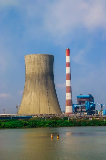
CTBD is a brackish stream enriched with sparingly soluble salts, and conventional brackish-water reverse osmosis (BWRO) is generally limited to 75–80% recovery before silica, CaCO3 and CaSO4 scaling become unmanageable; pushing higher with traditional layouts demands extra stages, interstage booster pumps, and recirculation loops that add cost, complexity and cleaning risk (S1). The engineering ceiling is not a membrane problem, it is a chemistry problem: the supersaturation that drives scaling lives in the concentrate, not on the membrane surface.
High-recovery designs break that ceiling by separating salt removal from osmotic-pressure limits. In the MAXH₂O Brine Desalter reference case, CTBD is treated through an RO stage operated conservatively below local scaling limits to produce reuse-quality permeate, while the concentrate is routed to a fluidized-bed reactor where scaling inhibitors are intentionally deactivated, allowing silica, CaCO3 and other problematic salts to precipitate onto seed material as compact pellets that leave the system as a solid waste stream (S1). The remaining brine is then primarily NaCl, which can be processed at much higher overall recovery. The reference case delivers ~95% overall recovery with permeate silica near 1 mg/L (S1). A second lever is dynamic RO operation, which alternates short production periods with brief, high-velocity flushes that keep the membrane inside the crystallization induction phase, extending chemical-cleaning intervals and avoiding interstage boosting entirely (S1).
For a Marseille-class site, this architecture translates into cooling-tower cycles well above the conventional 5–6 ceiling where biological and scaling risk normally force operators back down, reclaiming most CTBD as cooling-tower make-up and shrinking the freshwater withdrawal line. The relevant product lines for this stage are an industrial RO system for cooling tower blowdown plus the RO and UF membrane elements sized for high-recovery, scale-prone feed water.
Treatment Train by Stream: Gallery Pretreatment, CTBD Reuse, Sanitary, Heat-Export Condensate
Each Marseille stream has its own treatment duty, and the train has to be assembled stream by stream rather than as a single end-of-pipe solution. Gallery water from La Galerie de la Mer needs multi-media filtration to drop suspended solids and protect the plate heat exchangers and chillers, followed by chemical dosing for biofouling control and side-stream filtration on the closed chilled-water loop to keep particulates below the threshold that would erode the recovery rate of the downstream RO (S2, S4). An automatic chemical dosing system for scale and biocide control sits at this interface.
CTBD reuse is a two-stage separation problem before it becomes a membrane problem. Media filtration plus DAF pre-treatment ahead of the CTBD RO loop removes suspended solids, residual treatment chemicals and oils that would otherwise foul the high-recovery membranes, after which the clarified stream feeds the controlled-salt-precipitation RO loop described in the previous section. Permeate returns to the cooling tower as make-up; pellets leave as solid waste (S1, S4). Sanitary wastewater from the on-site population goes through a packaged MBR for site sanitary wastewater with PVDF membranes, delivering near-reuse-quality effluent suitable for toilet flushing or on-site irrigation and meeting EU Urban Waste Water Directive 91/271/EEC discharge criteria for BOD, TSS and total nitrogen. The heat-export condensate that crosses into the Dalkia Euroméditerranée district loop receives polishing filtration plus UV polishing on the heat-export condensate to keep corrosion products and biological regrowth off the secondary network (S5).
| Stream | Unit Operations | Effluent Target | Compliance Anchor |
|---|---|---|---|
| Gallery water | Multimedia filtration → chemical dosing → side-stream filtration | Low TSS, controlled biofilm, stable LSI on chilled water | Site IED permit envelope |
| CTBD reuse | Media filtration + DAF → controlled-salt-precipitation RO → dynamic flush RO | ~95% recovery, ~1 mg/L silica permeate | IED 2010/75/EU discharge envelope, French Arrêté on cooling water |
| Sanitary wastewater | Screening → packaged MBR (PVDF) → disinfection | BOD ≤25 mg/L, TSS ≤35 mg/L, total N ≤15 mg/L (typical UWWTD 91/271/EEC sensitive-area band) | UWWTD 91/271/EEC |
| Heat-export condensate | Polishing filtration → UV | Low Fe/Cu, low TOC, no biological regrowth | District-heating interface specification (Dalkia) |
Compliance Map: EU IED, UWWTD and French Cooling-Water Rules
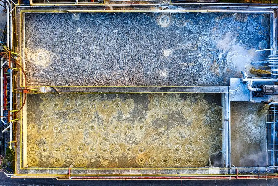
Three regulatory instruments frame the Marseille discharge envelope, and each treatment step maps to one of them. The EU Industrial Emissions Directive 2010/75/EU governs the cooling-tower and chiller discharge envelope, the EU Urban Waste Water Directive 91/271/EEC governs the on-site sanitary stream, and the French national rules transposing both at the site level set the local numerical limits and monitoring cadence. Any sea-facing brine disposal and any heat rejection to the Mediterranean sit inside the coastal discharge protections that overlay the IED permit (S1, S5).
The economic logic in the LCA literature is consistent with this compliance-first framing. A reuse train has roughly 2× the GWP of a freshwater train, with treatment energy accounting for ~80% of the difference, but the indirect water penalty is only ~0.93 L/m³, less than 0.1% of the direct displacement benefit, and under a fully decarbonized grid the GWP penalty becomes negligible while the water savings accrue at full value (S3). That is the right shape for a Marseille project: compliance, heat-export revenue and brand value dominate the board-level case, and freshwater savings are the supporting line rather than the headline. The crosswalk below ties the engineering work to the regulatory instrument. For a broader view of total-nitrogen thresholds relevant to the sanitary stream, see the global total nitrogen discharge compliance guide, and for the regulatory scaffolding outside the EU the UAE 2025 wastewater compliance guide offers a useful contrast.
| Regulatory Instrument | Applies To | Treatment Stage That Satisfies It |
|---|---|---|
| EU IED 2010/75/EU | Cooling-tower blowdown, chiller discharge, brine disposal | CTBD reuse loop, multimedia filtration, controlled-salt-precipitation RO |
| EU UWWTD 91/271/EEC | On-site sanitary wastewater | Packaged MBR with PVDF membranes |
| French Arrêté (cooling water) + coastal discharge protections | Heat rejection to sea, brine discharge envelope | CTBD reuse reduces volume; residue meets local discharge limits |
Marseille Implementation Roadmap and ROI Logic
The standard five-stage data-center water roadmap (measure → optimize → chemistry upgrade → modular blowdown reuse → advanced integration) compresses in Marseille because Stage 2 is largely already delivered by River Cooling (S4). The remaining work for a new MRS4-class site is to install monitoring on make-up, blowdown, evaporation and water-quality parameters, baseline consumption versus usage, and verify that actual blowdown runs within 15–30% of theoretical calculations (S4). From there the project moves to a chemistry upgrade that drops the dissolved-solids load on the blowdown stream, then to a modular blowdown-reuse system sized 100–300 GPM for a typical enterprise or colocation site, and finally to advanced integration that closes the cooling-tower loop on blowdown permeate with only evaporative losses requiring make-up (S4).
The ROI framing needs to be Marseille-specific. S4's 15 MW reference case shows a 6.7-year simple payback on water alone at $200,000 capex and 60% blowdown recovery, improving to 3–5 years once avoided discharge fees, heat-export revenue and WUE reporting value are included (S4). For Marseille, the headline is not water: it is the 18,400,000 kWh/yr saved by River Cooling, the 500,000 m² Euroméditerranée heat-export footprint, and the 1.11 PUE that lets the site win EU sustainability procurement frames (S2, S5). For procurement-level decisions on the dosing hardware, the automatic dosing pump selection guide and the sludge dewatering methods and efficiency data reference round out the engineering package.
Frequently Asked Questions
What does CTBD stand for and why is it a priority for a Marseille data center?
CTBD is cooling tower blowdown, the purge stream that prevents dissolved silica, calcium carbonate and calcium sulfate from scaling the cooling loop. At 4 cycles of concentration it equals 25% of make-up volume (S4), and in Marseille's closed chilled-water architecture it is the largest recoverable stream on site.
Why does Marseille use gallery water instead of direct seawater for free cooling?
La Galerie de la Mer is an 1885–1907 mining-drainage tunnel that discharges legacy mine water into the Mediterranean at a stable ~15°C year-round, so it gives Interxion's MRS2, MRS3 and upcoming MRS4 sites free-cooling 100% of the time (98.9% after maintenance) without the biofouling and corrosion exposure of raw seawater intake (S2, S5).
What recovery rate can BWRO achieve on cooling tower blowdown?
Conventional BWRO is limited to 75–80% recovery before scaling becomes unmanageable; chemistry-controlled designs such as the MAXH₂O Brine Desalter reach ~95% overall recovery with permeate silica near 1 mg/L by precipitating sparingly soluble salts as pellets before the residual NaCl brine is processed (S1).
Which EU and French instruments govern Marseille data center discharge?
The cooling-tower and chiller discharge envelope sits under EU Industrial Emissions Directive 2010/75/EU, the on-site sanitary stream is governed by EU Urban Waste Water Directive 91/271/EEC, and the French national rules transposing both set the local numerical limits alongside Mediterranean coastal discharge protections (S1, S5).
How does the heat-export loop change the water treatment scope?
Exporting heat into Dalkia's Euroméditerranée district network covering 500,000 m² of offices and housing requires polishing filtration plus UV on the condensate so that corrosion products and biological regrowth do not cross into the secondary district-heating network (S5).