
Why Montreal Data Centers Are a Unique Water Problem in 2026
A 100 MW AI hall in Greater Montreal draws up to 2 million litres of water per day from municipal potable supply, with about 20–25% leaving the site as cooling-tower blowdown once cycles of concentration (CoC) are set at 4–6 (per Ecologix, 2025-11). That blowdown stream is concentrated in silica, calcium hardness and treatment chemicals, and in 2026 it sits at the intersection of three local pressures: the active hyperscale build-out around Laval, Longueuil and the Cité de la Biotech corridor; the Jacques-Cartier and St. Lawrence wastewater plants that already serve a large industrial base; and a regulatory framework that has tightened substantially under Quebec's Règlement sur les effluents des systèmes d'assainissement des eaux usées (REAFIE) and the federal Fisheries Act prohibition on deleterious discharge.
Montreal's climate cuts both ways. Cold winters lower evaporative loss, so the blowdown volume per kWh shrinks and CoC is naturally easier to hold — a counter-intuitive operational benefit compared with Phoenix or Dallas. The trade-off is that blowdown lines, outdoor DAF skids, clarifier launders and any exposed chemical dosing headers must be heat-traced, insulated, or moved indoors, and freeze-protection becomes a baseline design constraint rather than a footnote. Roughly 70% of Canadian data centres draw from municipal potable (per Ecologix field data, 2025-11), so any design that ignores the aqueduct-side constraint will run into the same supply conversation already happening in Longueuil's 2026 capacity hearings.
The performance benchmark to design against is Water Usage Effectiveness (WUE) of 1.8 L/kWh for an efficient facility, with the broader North American band running 1.8–2.5 L/kWh. A 50 MW site at PUE 1.2 hits roughly 1.8 million L/day of total water use, of which about 0.45–0.55 million L/day is blowdown. If a sustainability lead quotes 0.47 US gal/kWh (≈ 1.8 L/kWh) as "industry average," they are quoting the lower bound of the band — the design target should sit there or below, not at it.
What's Actually in Cooling-Tower Blowdown — and Why It Matters Here
Cooling-tower blowdown is the concentrated liquor left behind when pure water evaporates and dissolved species do not. In a Montreal AI hall running at 4–6 CoC, that stream typically carries up to ~2,000 ppm total dissolved solids (TDS), elevated silica, calcium hardness, alkalinity, and a chemical residual load — phosphonate antiscalants, molybdate corrosion inhibitors, oxidizing biocides, plus leached copper and zinc from metallurgy in the loop (per Ecologix case data, 2025-11). Effluent temperature runs 30–40°C above intake, which is exactly the band that triggers the <5°C ΔT discharge rule applied to most Quebec receiving-water permits.
Biofouling in the loop follows first-order kinetics, dC/dt = −kC, with k between 0.1 and 0.5 h⁻¹ depending on temperature and nutrient load. Montreal's cold intake water suppresses the upper end of that range, which lets operators run leaner biocide programs, but the moment cooling-tower fill or basin water warms above ~25°C in summer, the kinetics accelerate. CIP frequency has to be planned for the worst-case summer week, not the annual average.
Scale control rests on the carbonate equilibrium Ca²⁺ + 2HCO₃⁻ ⇌ CaCO₃↓ + CO₂ + H₂O. The Langelier Saturation Index (LSI) is targeted between −0.5 and +0.5; the Ryznar Stability Index (RSI = 2pHs − pH) is the cross-check for under-saturated, corrosion-prone conditions. Inline LSI monitoring with PLC feedback to the antiscalant dosing pump is the standard control loop; manual trim by jar test once per quarter is the audit trail.
The WUE math is worth showing explicitly. For a 100 MW facility at PUE 1.2: IT load = 100 / 1.2 ≈ 83.3 MW, daily IT energy = 83.3 × 24 = 2,000 MWh, and at 1.8 L/kWh the daily site water use is 1.8 × 2,000,000 = 3,600,000 L. With evaporation at roughly 60% of total draw and the balance as blowdown at 4–6 CoC, the blowdown fraction is 20–25% of makeup — not the 50% figure that often gets quoted in board decks.
| Parameter | Typical Montreal Range | Source / Basis |
|---|---|---|
| TDS in blowdown | 1,200–2,000 ppm at 4–6 CoC | Ecologix case data, 2025-11 |
| Effluent temperature | 30–40°C above intake | Ecologix, 2025-11 |
| Biofouling rate constant k | 0.1–0.5 h⁻¹ | Standard first-order biofouling model |
| LSI target | −0.5 to +0.5 | Reuse industry standard |
| RSI (corrosion cross-check) | 5.5–7.0 (no severe scaling) | Standard cooling-water practice |
| ΔT vs receiving water | <5°C | Typical Quebec permit condition |
The 2026 Montreal Treatment Train: Pretreatment → Membrane → Brine Management
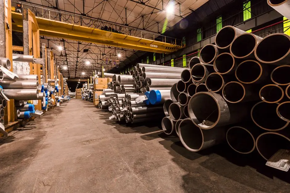
The treatment train below is the unit-operation-level P&ID an engineer in Montreal can lift directly into a design basis. Each stage carries a specific Montreal-relevant rationale, including the cold-climate placement note that determines whether the unit lives indoors, in a heated enclosure, or fully buried.
Stage 1 — Source conditioning. A vertical multi-media filter for SDI reduction brings silt density index below 5 ahead of the membranes, followed by a twin-tank industrial softener for makeup hardness control on sodium-cycle ion exchange to take calcium and magnesium off the board before the RO. PLC-controlled antiscalant and biocide dosing skids trim LSI to the −0.5 to +0.5 band and feed oxidizing biocide on a timer; in Montreal, both skids belong indoors or in a heated pump house to keep metering accuracy and prevent sodium sulfite or bisulfite stock from freezing.
Stage 2 — Pretreatment polish. PVDF ultrafiltration as RO pretreatment at 0.03 μm on hollow-fibre modules rides through turbidity upsets up to ~300 NTU, with automatic backwash and air-scour cycles sized to handle the suspended load in the softener effluent. The UF stage is the buffer that lets the RO run at design flux without colloidal or biological fouling, and in a Montreal winter it lives in a heated skid room — not outdoors.
Stage 3 — Primary separation. Brackish RO units sized to Montreal blowdown duty run at a conservative 75–80% local recovery, governed by the flux equation Jw = A(ΔP − Δπ), with Δπ ≈ 0.4 MPa at 500 ppm TDS feed. Permeate is already reuse-quality cooling-tower makeup. High-pressure pump discharge lines are heat-traced and insulated from the feed turbocharger to the membrane vessel, since RO pumps cannot tolerate stagnant cold-start excursions on the concentrate side.
Stage 4 — Brine management. RO concentrate is routed either to a brine concentrator / forced-circulation crystallizer or, more commonly at Montreal scale, to a fluidized-bed reactor where silica and calcium carbonate are intentionally precipitated onto seed pellets at elevated pH. The reactor is operated with the antiscalant chemistry deliberately deactivated, which is the engineering trick that pushes overall system recovery from 80% toward 90–95% with permeate silica around 1 mg/L (per IDE field data, 2025). The reactor itself is skid-mounted and insulated; the seed-pellet withdrawal hopper is the only piece that has to be inside a heated, ventilated room.
Stage 5 — Polishing and disinfection. On the reuse loop, UV or chlorine dioxide controls microbial regrowth in the cooling-tower makeup. On the discharge path, pH adjustment and a dissolved air flotation unit for residual TSS knock down any carry-over solids before the stream reaches the combined sewer. The DAF and any sludge-handling equipment (e.g., plate-frame filter press for sludge dewatering and high-efficiency sedimentation tank for the clarifier underflow) need to be inside an insulated enclosure for January operations.
| Stage | Unit Operation | Key Parameter / Target | Montreal Placement |
|---|---|---|---|
| 1 | Multi-media filter + softener + dosing | SDI <5; LSI −0.5 to +0.5 | Indoor pump house |
| 2 | UF (PVDF, 0.03 μm) | Turbidity upset to ~300 NTU | Heated skid room |
| 3 | Brackish RO | 75–80% recovery, Δπ ≈ 0.4 MPa at 500 ppm | Heat-traced HP piping |
| 4 | Fluidized-bed brine reactor / crystallizer | 90–95% overall recovery, permeate SiO₂ ~1 mg/L | Insulated skid, heated hopper |
| 5 | UV / ClO₂ + pH trim + DAF | Microbial control on reuse; TSS polish on discharge | Insulated enclosure |
Meeting Quebec & Federal Compliance in 2026
Three regulatory layers govern a Montreal blowdown discharge in 2026, and the design has to clear all three.
At the provincial level, MELCCFP administers industrial-effluent discharge through the REAFIE framework, which sets numeric ceilings on conventional pollutants, metals, temperature, pH and whole-effluent toxicity for any stream entering a municipal sewer or surface water. The City of Montréal's sewer-use bylaw (11-018 and its successors) layers on local sanitary-sewer limits — typically tighter than REAFIE on TDS, zinc, copper and temperature — and is the document the plant operator reads first. On top of both sits the federal Fisheries Act prohibition on depositing deleterious substances into water frequented by fish, which is the legal backstop for any direct discharge path to the St. Lawrence.
On-site treatment becomes mandatory, not optional, when one of three conditions is met: the permit ceilings on TDS or ΔT are tighter than what the blowdown can meet with municipal dilution alone; the facility has committed to a water-reuse or Zero-Liquid-Discharge (ZLD) target in its ESG disclosures; or the receiving wastewater plant lacks hydraulic capacity. The third condition is the one driving the Laval and Longueuil conversations in 2026 — daily blowdown of 1.14–1.70 million litres is the order of magnitude that strains a small WWTP, and the local utility will not accept a new large customer without a treatment-side story. Quebec permit conditions also typically require a monitoring plan, a baseline characterization report and annual compliance reporting — a documentation burden, not a federal one, that the design has to budget for.
| Authority | Instrument | What It Controls |
|---|---|---|
| MELCCFP (provincial) | REAFIE | Industrial-effluent ceilings, toxicity, metals |
| City of Montréal (municipal) | Sewer-use bylaw 11-018 | Sanitary-sewer limits (TDS, Zn, Cu, ΔT) |
| Fisheries Act (federal) | Section 36(3) prohibition | Deleterious discharge to fish-bearing water |
Sizing & Cost Example: A 50 MW Montreal AI Hall
Working from a 50 MW heat load at 80% cooling-tower efficiency, the evaporation rate E = (50,000 × 860) / (2,257 × 0.8) ≈ 99,537 kg/h (per Ecologix, 2025-11). Blowdown is B = E / (CoC − 1), so at 4 CoC, B = 99,537 / 3 ≈ 33,179 kg/h; at 6 CoC, B = 99,537 / 5 ≈ 19,907 kg/h. Translating to a 24-hour day, daily blowdown is roughly 796,000 L at 4 CoC and 478,000 L at 6 CoC — a 40% reduction in blowdown volume, not the 50% often quoted by operations teams that confuse the relative reduction with the blowdown ratio itself.
Blowdown as a fraction of total makeup is 1/(CoC) at steady state in the simple model, which works out to 25% at 4 CoC and 20% at 6 CoC — the real saving is 5 percentage points of makeup, achievable only if the chemistry and microbiology stay under control. Above CoC 5–6, scaling risk, biological fouling and chemical cost all rise steeply, and many sites find themselves forced back down to a sustainable CoC.
Order-of-magnitude CAPEX for a modular UF + RO system on a 10 MW colocation site sits in the low-to-mid six figures USD. A 50–100 MW hyperscale installation that includes brine concentration and a full reuse loop scales into the multi-million CAD range; membrane replacement alone (using elements from a replacement RO/UF membrane elements program) typically runs 8–15% of CAPEX per year. OPEX is dominated by chemical cost above CoC 5–6, energy for high-pressure RO pumps, and labour for membrane CIP cycles. Simple payback lands in the 3–5 year band when avoided potable, sewer and compliance costs are included, which is the number a finance committee in Montreal will accept for a 2026 CAPEX submission.
| Metric | 4 CoC | 6 CoC |
|---|---|---|
| Evaporation E (kg/h) | 99,537 | 99,537 |
| Blowdown B (kg/h) | 33,179 | 19,907 |
| Daily blowdown (L/day) | ~796,000 | ~478,000 |
| Blowdown as % of makeup | 25% | 20% |
| OPEX chemical profile | Baseline | Rises sharply above CoC 5–6 |
Frequently Asked Questions
What wastewater and cooling blowdown treatment does a data center in Montreal, Canada need in 2026?
A 2026-compliant Montreal data center runs a five-stage train: multi-media filtration plus softening, PLC-controlled antiscalant and biocide dosing, PVDF ultrafiltration, brackish reverse osmosis at 75–80% local recovery, and a brine concentrator or fluidized-bed reactor to push overall recovery to 90–95%. The permeate is reused as cooling-tower makeup; the concentrate is handled as a solid waste. Start by mapping the facility's WUE against the 1.8 L/kWh benchmark and a CoC of 4–6.
Which Quebec regulations govern cooling-tower blowdown discharge?
Three layers apply: MELCCFP's REAFIE framework for industrial-effluent ceilings, the City of Montréal sewer-use bylaw 11-018 for sanitary-sewer limits, and the federal Fisheries Act prohibition on deleterious discharge. Engineers should also confirm whether the Jacques-Cartier or local WWTP has hydraulic capacity for a new large customer. First step: request a copy of bylaw 11-018 and the REAFIE schedule for the relevant industrial sector.
How much does a data-center blowdown treatment system cost in Montreal?
A modular UF + RO system for a 10 MW colocation site is in the low-to-mid six figures USD; a 50–100 MW hyperscale installation with brine concentration runs into the multi-million CAD range. Simple payback lands at 3–5 years once avoided potable, sewer and compliance costs are counted, which is the threshold for Montreal-area CAPEX committees in 2026. Next step: build a total-cost-of-water model that includes the bylaw 11-018 sewer surcharge.
Can a Montreal data center achieve Zero Liquid Discharge?
Yes, but the CAPEX delta is significant. Achieving ZLD means adding a brine concentrator and either a crystallizer or a fluidized-bed precipitation reactor to push recovery past 95%, then handling the solid residue as a waste stream. The economics work when potable cost, sewer cost and ESG commitments stack up — typical for AI-hall builds around Laval and Longueuil. For a comparable cold-climate reference, see the Rio de Janeiro data-center blowdown treatment guide and the Brasília data-center blowdown treatment playbook.
How does Montreal's compliance regime compare with Calgary's?
Both fall under provincial and federal frameworks, but Calgary operates under Alberta Environment's codes while Montreal answers to MELCCFP and bylaw 11-018. Cold-climate placement rules (indoor skids, heat-traced HP piping) are similar; the discharge ceilings diverge on metals and TDS. For a side-by-side engineering read, the Calgary ETP engineering and compliance reference is the closest Canadian comparator. Next step: pull the Calgary and Montreal permit conditions for the same IT load and benchmark.