
Regulatory Stack a Marcy-Area Fab Must Clear Before Sewer Discharge
A Marcy-area fab discharges into a publicly owned treatment works (POTW) governed by three nested authorities, and the design must clear all three before a single gallon leaves the site. The federal anchor is 40 CFR 403 (General Pretreatment Regulations), which establishes Categorical Standards, Local Limits, Industrial User Permitting, the Significant Industrial User (SIU) vs. Categorical Industrial User (CIU) thresholds, Best Management Practices (BMPs), and slug-control plan requirements (per EPA 40 CFR 403). New York's state layer runs through the NYSDEC SPDES permit program, the requirements of 6 NYCRR Part 750, and the emerging PFAS designations (PFOA, PFOS, GenX, PFNA) under the 6 NYCRR Part 700-series, as well as state hazardous-waste rules under 6 NYCRR Part 370 that apply to spent chemistries and brine residues. The local layer is the Oneida County Sewer District Sewer Use Ordinance, which sets the binding numerical limits at the sewer manhole: pH 5–11, oil and grease ≤100 mg/L, TSS typically capped near 250 mg/L, plus metals (Cu, Ni, Pb, Zn) and fluoride targets enforced at the discharge manhole. The receiving POTW (Sauquoit Creek WPCF / Oneida County WPCP) then applies its own headworks capacity and slug-load procedures before the flow reaches the headworks.
Two federal industrial-policy factors raise the bar in 2026. First, Wolfspeed's Marcy, NY facility is the only fully dedicated 200 mm SiC fab in the world (Wolfspeed, Section 232 filing, 2025-08), which means the receiving POTW will scrutinize fluoride, ammonia, and slurry loadings from a single very large point source. Second, the January 2026 Section 232 proclamation on semiconductors (White House, 2026-01) conditions any tariff relief on demonstrated domestic supply-chain investment, so pretreatment performance is now a permitting data point that federal economic and national-security reviewers can pull. The categorical standards for SIC 3674 (Semiconductors and Related Devices) and SIC 2819 (Industrial Inorganic Chemicals) interlock with 40 CFR 403 whenever a fab holds its own SIU permit, so the engineer should expect the local POTW to enforce both sets of numerical limits at the manhole.
Why SiC Fabs Discharge a Different Wastewater Than Silicon-Logic Fabs
SiC processing produces a wastewater fingerprint that a logic-fab treatment train was not sized for. Etching uses hot HF/HNO₃ mixtures to remove silicon carbide, generating a fluoride-bearing acid stream far more aggressive than the dilute HF rinses of a silicon logic line. CMP on SiC and SiO₂ generates a dense, abrasive slurry that fouls membranes and clogs fine-bubble diffusers. Deposition of SiN and AlN PECVD layers releases ammonia into the scrubber blowdown, while metallization introduces trace Ni, Ti, and W that have to be removed before discharge. Solvent cleaning with isopropanol and NMP, plus photoresist strip waste, adds a high-COD, low-pH stream that is incompatible with the fluoride line. The combined waste stream carries HF, HCl, H₂SO₄, NH₃, Cu/Ni/W, CMP slurry, solvents, photoresists, fluorides, and PFAS (per IDE Technologies, 2026).
The volume profile is large: a modern fab uses up to 10 million gallons/day (per IDE Technologies, 2026), and CMP alone is 30–40% of total wastewater volume. These streams are not mixable. HF reacts with ammonia to form ammonium bifluoride deposits inside piping, and acids mixed with solvents create exothermic separation problems. pH swings across the day routinely cross four units, and the abrasive solids chew up pump impellers and RO feed spacers. The engineering rule that follows is unavoidable: segregated collection systems, each routed to a dedicated treatment line, must be in place before any centralized recovery or discharge. A single combined equalization basin would force the designer to handle every incompatibility at once. A DAF system for CMP slurry removal sitting on the slurry branch is the practical way to isolate the abrasive load before it ever meets the acid line.
The Segregated Treatment Train: Stream-by-Stream Design
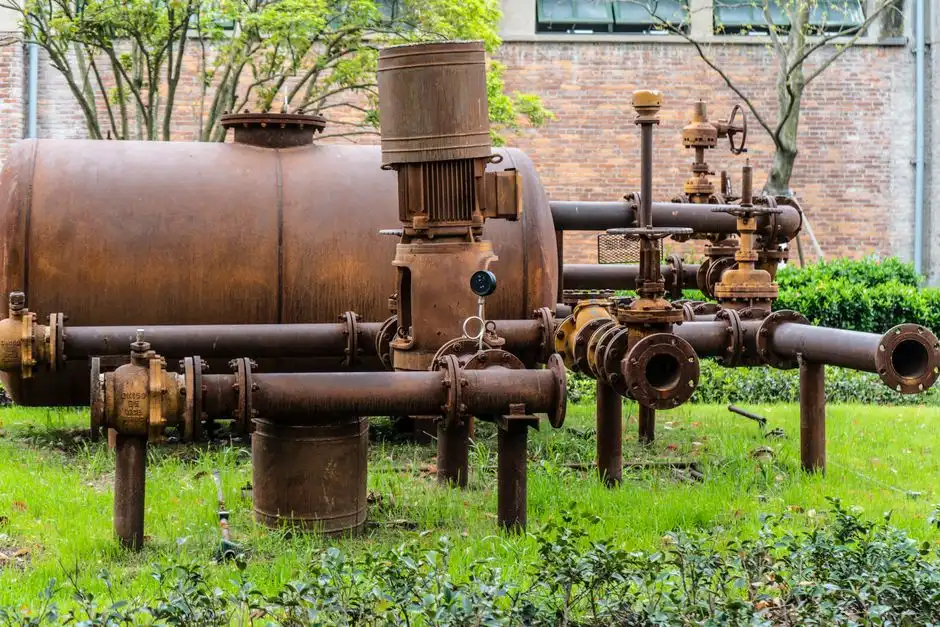
Five segregated branches feed a centralized metals-polishing and RO finishing skid. The acid/alkali line runs through a two-stage neutralization train: equalization tank, then caustic or acid dosing into a lamella clarifier for acid/alkali neutralization, with the pH controller targeting 6–9 to land inside the sewer-use 5–11 envelope. The fluoride-bearing line uses calcium- or aluminum-based precipitation to drop fluoride below the local limit, followed by a multi-media filter for SDI reduction ahead of RO; HF attacks glass, so all wetted parts in this branch must be lined FRP, PP, or PVDF. The CMP slurry line uses a DAF clarifier first to float the bulk solids, then 0.1 µm UF for submicron particle polishing before RO. The solvent/photoresist line routes through an API oil-water separator, equalization, then biological treatment or an AOP skid (UV/H₂O₂, ozone, or catalytic) that breaks down photoresists, solvents, and surfactants via hydroxyl-radical oxidation (per IDE Technologies, 2026) before membrane polishing. The ammonia-bearing line uses breakpoint chlorination (Cl:N ratio ~7.6:1 to 8:1 by weight) or a biological A/O or AAO train to hit NH₃-N discharge limits.
All five branches reconverge at a centralized metals-polishing skid: pH/sulfide or hydroxide precipitation → sand filter → cartridge guard → RO. A PLC-controlled chemical dosing skid for pH, fluoride, and metals precipitation ties online pH, ORP, fluoride ion-selective electrodes, and metals analyzers into closed-loop trim control. The table below summarizes the parameter targets the designer should be working to at each stage.
| Stream | Primary Unit Process | Polishing Step | Effluent Target | Design Driver |
|---|---|---|---|---|
| Acid/alkali | Equalization + two-stage pH neutralization (lamella) | Sand filter | pH 5–11 | Oneida County Sewer Use Ordinance |
| Fluoride-bearing | Ca²⁺/Al³⁺ precipitation | Multi-media filter → RO | F⁻ < local limit (site-specific) | 40 CFR 403 local limits; HF-resistant materials |
| CMP slurry | DAF + lamella | UF 0.1 µm | TSS < 250 mg/L trend | Oneida County local limit; SDI protection for RO |
| Solvent/photoresist | API OWS + equalization | Biological or AOP → RO | COD < local limit; oil & grease ≤100 mg/L | Local sewer use; TOC < 1 mg/L for UPW reuse |
| Ammonia-bearing | Breakpoint chlorination or A/O | Sand filter | NH₃-N < site limit (often 10–20 mg/L trend) | NYSDEC SPDES; POTW headworks protection |
| Centralized metals | Hydroxide/sulfide precipitation | Cartridge → RO | Cu/Ni/Zn at local limits | 40 CFR 403 categorical; local limits |
Parameter Table: Influent, Unit Process, Effluent, Compliance Basis
The reference table below is sized to be paste-ready into a PFD or a basis-of-design memo. Values are typical 2026 design targets for a Marcy-area SiC fab, not site-specific permit limits. The site-specific values are set by the local POTW and the SPDES permit.
| Parameter | Typical Influent to Treatment | Unit Process | Effluent Target (Manhole) | Compliance Basis |
|---|---|---|---|---|
| pH | 1–13 (per stream) | Two-stage neutralization + lamella | 5–11 | Oneida County Sewer Use Ordinance |
| TSS | 200–1,000 mg/L | DAF + lamella + UF | ≤250 mg/L | Local sewer use; 40 CFR 403 |
| Fluoride (F⁻) | 50–500 mg/L (etch branch) | Ca²⁺ precipitation + MMF + RO | Per local limit (often < 10–25 mg/L trend) | 40 CFR 403 local limits; NYSDEC SPDES |
| NH₃-N | 20–200 mg/L | Breakpoint chlorination or A/O | Per SPDES permit (often 10–20 mg/L trend) | NYSDEC SPDES; POTW headworks |
| COD | 200–1,500 mg/L (solvent line) | Biological / AOP + RO | Per local limit (often < 300–500 mg/L trend) | Oneida County Sewer Use Ordinance |
| Cu | 1–20 mg/L | Hydroxide/sulfide precipitation + RO | Per categorical/local limit (≤1–3 mg/L typical) | 40 CFR 403 categorical; local limits |
| Ni | 1–10 mg/L | Hydroxide precipitation + chelating resin + RO | Per categorical/local limit (often < 1 mg/L) | 40 CFR 403; NYSDEC |
| Zn | 1–20 mg/L | Hydroxide precipitation + RO | Per local limit (often < 2–5 mg/L) | 40 CFR 403 local limits |
| Oil & grease | 50–500 mg/L (solvent line) | API OWS + DAF | ≤100 mg/L | Oneida County Sewer Use Ordinance |
| Total FOG | 50–300 mg/L | API OWS + biological | ≤100 mg/L | Local sewer use |
| Flow | Site-specific (up to 10 MGD site total; CMP 30–40%) | Equalization + RO | Per SIU permit (per IDE Technologies, 2026) | NYSDEC SPDES; SIU permit |
PFAS, ZLD, and the 85–90% Recovery Target
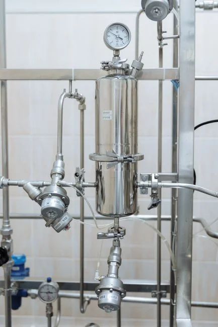
PFAS handling is no longer optional for a 2026 fab design. EPA's PFAS roadmap has established legally binding MCLs and designated PFOA and PFOS as CERCLA hazardous substances (per EPA roadmap summarized by IDE Technologies, 2026), and New York's 6 NYCRR Part 700-series designations cover the same compound list. The design must destroy PFAS, not simply transfer it to spent media. A defensible stack runs high-pressure RO or nanofiltration first, followed by activated-carbon adsorption or ion-exchange resin, terminated by an AOP stage that mineralizes the desorbed organics rather than sending them to a landfill. AOPs generate hydroxyl radicals (•OH, oxidation potential ~2.8 V) that convert photoresists, solvents, surfactants, and PFAS precursors into CO₂ and water, which protects downstream RO from organic fouling and lets the same skid serve both pretreatment and water-reuse duties.
Recovery is the second pillar. State-of-the-art fabs recover 85–90% of their wastewater using high-recovery RO, advanced filtration, and thermal polishing (per IDE Technologies, 2026). ZLD takes that residual 10–15% through brine concentrators and crystallizers, eliminating any liquid sewer discharge for the recovered fraction. For a Marcy-area fab facing Section 232-driven federal scrutiny plus tightening PFAS rules, ZLD is the most defensible long-term path: it converts a pretreatment permit question into a water-stewardship answer. High-recovery industrial RO for fab polishing paired with a ClO₂ generator for biological polishing effluent disinfection stage is a workable 2026 reference configuration. The table below compares the realistic PFAS options on the same axis.
| PFAS Treatment Option | Removal Mechanism | Destroys or Transfers? | Residual Handling | 2026 Suitability |
|---|---|---|---|---|
| High-pressure RO / NF | Size exclusion | Transfers to concentrate | Send to AOP or thermal brine | Front-end of stack |
| Activated carbon (GAC) | Adsorption | Transfers to spent carbon | Spent-media disposal | Defensible, but media disposal is a liability |
| Ion-exchange resin | Selective sorption | Transfers to resin | Regenerant to AOP | Good for trace polishing |
| AOP (UV/H₂O₂, O₃, catalytic) | Hydroxyl-radical oxidation | Destroys (mineralizes) | CO₂ + water + simpler organics | Required for true destruction |
| Thermal (evaporator/crystallizer) | Phase change | Concentrates; salts recovered | Solid waste (ZLD) | Back end of ZLD stack |
Equipment Checklist and Spec Boundaries for a 2026 Pretreatment Skid
The equipment list below should be reviewable in a single procurement meeting. DAF / lamella clarifier: surface loading 20–40 m/h on the lamella, micro-bubble DAF on the CMP branch for oil-and-grease removal and slurry handling. Multi-media filter: target SDI <3 to protect downstream RO, automatic backwash, long-life anthracite/sand/garnet media. RO system: recovery up to 95% with PLC control, FRP membrane housings for fluoride service, continuous online conductivity monitoring. Chemical dosing skid: PLC-controlled injection of coagulant, flocculant, pH adjusters, and specialty chemistries (CaCl₂ for fluoride precipitation, NaOH/HCl for neutralization, sulfide for heavy-metal polishing). Disinfection: on-site ClO₂ generation for biological polishing effluent, sized for both reuse and discharge duty, compliant with EPA and EU drinking-water standards.
| Equipment | Key Spec Boundary | Linked Role in the Train |
|---|---|---|
| DAF system | Surface loading 20–40 m/h; micro-bubble | CMP slurry removal, O&G stripping |
| Lamella clarifier | High-rate, lined FRP/PP for HF | Acid/alkali neutralization; fluoride precipitation |
| Multi-media filter | SDI <3 outlet; auto backwash | RO pretreatment, TSS polishing |
| Industrial RO | Up to 95% recovery; FRP housing for F⁻ | Dissolved solids, metals, anion polishing |
| Chemical dosing skid | PLC, redundant pumps, online analyzers | pH, fluoride, metals precipitation trim |
| Plate-and-frame filter press | Solids dewatering to < 60% moisture trend | Sludge handling from DAF/lamella |
| Mechanical bar screen | Headworks protection, 2–6 mm opening | Solids removal ahead of equalization |
| ClO₂ generator | EPA/EU compliant sizing | Disinfection of polished effluent |
For broader context on full-train economics, see our chip fab ZLD engineering specs and cost data, our monocrystalline silicon wastewater MBR-RO specs, and the HF wastewater treatment cost breakdown and ROI guide; electronics plants looking for a hybrid reference should also review hybrid DAF-RO-MBR supplier specs for electronics wastewater.
Frequently Asked Questions
What regulatory authority actually sets the binding limits for a Marcy-area fab discharging to a POTW?
The binding numerical limits at the sewer manhole come from the Oneida County Sewer District Sewer Use Ordinance, enforced through the local POTW's SIU permit. Federal 40 CFR 403 and any applicable Categorical Standards set the floor, and the NYSDEC SPDES permit layers state-level requirements on top, including emerging PFAS designations under 6 NYCRR Part 700 (per EPA 40 CFR 403; NYSDEC SPDES).
Which waste streams dominate volume and contaminant load at a SiC fab?
At a modern SiC fab, total wastewater can reach 10 million gallons per day, and CMP slurry alone is typically 30–40% of that volume. The other major branches are acid/alkali (HF, HCl, H₂SO₄), fluoride-bearing etchant, ammonia-bearing scrubber blowdown, and solvent/photoresist waste (per IDE Technologies, 2026).
How does a 2026 fab handle PFAS in pretreatment without creating a spent-media disposal problem?
The defensible 2026 approach is a high-pressure RO or NF front end, followed by activated carbon or ion exchange for polishing, terminated by an AOP stage (UV/H₂O₂, ozone, or catalytic) that mineralizes the desorbed PFAS to CO₂ and water rather than transferring it to spent media (per IDE Technologies, 2026).
What recovery rate should a Marcy-area fab target in its basis-of-design memo?
State-of-the-art fabs recover 85–90% of their wastewater through high-recovery RO, advanced filtration, and thermal polishing, with ZLD driving the residual 10–15% to brine concentrators and crystallizers for zero liquid sewer discharge (per IDE Technologies, 2026).