Why Senatobia Petroleum Plants Are Rethinking the Clarifier in 2026
For Senatobia-area plants in 2026, the choice between a DAF clarifier and a conventional gravity clarifier is no longer a coin flip — it is set by the specific gravity of the contaminant. Free and emulsified oil, FOG, and fine suspended solids with specific gravity near or below 1.0 physically cannot settle in a gravity vessel, so the old clarifier default is producing out-of-spec effluent for most Tate County lube-oil blenders, terminals, small refineries, and metalworking shops discharging under the Mississippi Department of Environmental Quality (MDEQ) Industrial Stormwater and NPDES pretreatment framework. DAF reverses the separation — it floats what will not sink — and hits 92-97% TSS removal and up to 95% FOG removal on a plan area that is only 20-25% the size of a comparably rated clarifier (Hydropure 2025). The 2026 question for a Senatobia operations manager is therefore narrow: keep an aging clarifier and dose more coagulant to chase a compliance margin that gets thinner every permit cycle, or replace it with a DAF clarifier and recover footprint, sludge quality, and reuse potential in the same move.
What a DAF Clarifier Actually Does to an Oily Stream
A DAF clarifier is a four-stage engineered sequence — coagulation/flocculation, air dissolution, bubble-particle attachment, and flotation/skimming — and understanding each stage is what separates a defensible spec from a catalog purchase. In stage one, cationic or anionic polymer at 0.5-5 mg/L bridges dispersed oil droplets and fine TSS into buoyant flocs large enough to be lifted. In stage two, a recycle pump takes 10-30% of the clarified effluent, pressurizes it to 4-6 bar, and saturates it with air at 85-95% saturation efficiency inside a dissolution tank. In stage three, that pressurized recycle enters the flotation cell at atmospheric pressure, and the dissolved air comes out of solution as 20-100 μm micro-bubbles that nucleate on the floc surfaces. In stage four, the bubble-floc aggregates rise in 3-5 minutes and are skimmed into a float trough as a 3-5% solids cake.
The mechanism explains the performance numbers. Micro-bubbles in the 20-100 μm window provide enough surface area to attach to sub-50 μm oil droplets — exactly the size range that slips past an API oil-water separator and defeats a clarifier. Surface loading rates of 5-15 m/h are 5x higher than a clarifier's 1-3 m/h, which is why the same 50 m³/h stream fits on a footprint one-fifth the size. The output is up to 95% FOG removal and 92-97% TSS removal (HydropureWater field data, 2025), with float solids dry enough to cut downstream hauling by 50-70% versus a clarifier underflow. The right anchor unit for a Senatobia plant is a DAF clarifier sized to the 4-300 m³/h band, paired with an automatic polymer dosing skid so the 0.5-5 mg/L charge stays in the operating window without an operator babysitting a drum pump.
What a Conventional Clarifier Still Does Well
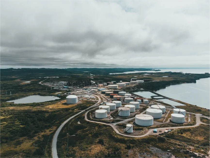
A conventional clarifier is a passive concrete or steel vessel that relies on 2-4 hours of hydraulic retention and a density differential between particle and water to drop solids to the bottom. There is no compressor, no recycle loop, no polymer, and very little to fail — which is exactly why it has been the pretreatment default for fifty years. The honest performance ceiling, however, is 40-60% TSS on light, oily, or fibrous streams, with 1-2% underflow solids that load downstream dewatering and haul-off costs. A clarifier cannot drop an oil droplet — oil floats, not sinks — so any stream carrying free oil, emulsified oil, FOG, or fine fibers leaves the clarifier largely untouched and pushes the cleanup burden to the next stage.
The clarifier still wins in a narrow band of influents. Heavy inorganic grit from a truck wash, sand from a metalworking floor, or metal shavings from a machining cell are denser than water and settle reliably with minimal chemical spend, so a lamella plate stack or a basic clarifier delivers the lowest CAPEX per gallon treated. The penalty is footprint — typically 4-5x the DAF plan area for the same throughput (Hydropure 2025) — and the inability to handle slug loads of oil when a process tank dumps. For those streams, a lamella clarifier as a first stage is still the right call; for anything with oil in the influent, it is not.
DAF vs Clarifier for Petroleum Wastewater: Side-by-Side Comparison
The table below condenses the mechanism discussion into the parameters a Senatobia procurement manager will be asked about in a CAPEX review. Every row is pulled from Hydropure's 2025 engineering data or the SSRN 2022 study on DAF-MMBBR for synthetic oily wastewater (S2) and cross-checked against Ecologix's produced-water reference (S3) so the numbers are not vendor-only.
| Parameter | DAF Clarifier | Conventional Clarifier |
|---|---|---|
| TSS removal | 92-97% | 40-60% |
| FOG / oil removal | Up to 95% | <30% (oil floats, not sinks) |
| Surface loading rate | 5-15 m/h | 1-3 m/h |
| Footprint (same flow) | Baseline | 4-5x larger |
| Sludge / float solids | 3-5% float | 1-2% underflow |
| CAPEX band (4-300 m³/h) | $50,000-$500,000 | Lower (vessel-only) |
| Energy use | 0.2-0.5 kWh/m³ | Negligible (passive) |
| Chemical use | 0.5-5 mg/L polymer | Minimal to none |
| Operator skill needed | Moderate (chemistry + pressure) | Low |
| Best-fit influent | Free/emulsified oil, FOG, fine TSS | Heavy grit, sand, metal shavings |
| Choose DAF when… | Oil, FOG, or emulsified droplets dominate; footprint is constrained; reuse is a goal | — |
| Choose Clarifier when… | — | Influent is heavy inorganic grit, CAPEX must be minimized, and chemical spend must stay near zero |
The bottom two rows are the decision rule a buyer can paste into a memo. Both the SSRN 2022 paper (S2) and Ecologix's oil-and-gas page (S3) confirm DAF as the standard for emulsified oil and produced water — this is not vendor positioning, it is the published baseline for refinery pretreatment.
2026 Cost Model: CAPEX, OPEX, and ROI for a Senatobia-Sized Plant

Translating the matrix into 2026 dollars is the part of the conversation that actually closes a CAPEX meeting. The table below uses the DAF 4-300 m³/h band, the Hydropure 2025 OPEX framework, and a worked example for a 50 m³/h stream — a typical mid-sized lube-oil blender or small refinery outfall in the Senatobia area.
| Cost line | DAF Clarifier (50 m³/h) | Conventional Clarifier (50 m³/h) |
|---|---|---|
| CAPEX — equipment + install | $120,000-$180,000 (SS316 wetted parts, PLC) | $60,000-$110,000 (concrete/steel vessel) |
| Energy | 0.2-0.5 kWh/m³ → ~$3,500-$8,800/yr at MS industrial rate | Marginal (scum/sludge pumps only) |
| Polymer | 0.5-5 mg/L → ~$2,000-$6,000/yr | None |
| Sludge hauling | 3-5% float → ~50-70% fewer hauls → ~$40,000/yr saved vs clarifier baseline | 1-2% underflow → baseline disposal cost |
| Annual OPEX delta vs clarifier | Net negative $25,000-$35,000/yr after disposal savings | Baseline |
| Payback window | 1.5-3 years (Hydropure 2025 framework) | — |
The headline number is the hauling line: drier float at 3-5% solids collapses the volume of waste trucked off-site by 50-70% (Hydropure 2025), and at Mississippi disposal rates that is the line item that flips the ROI calculation. The same logic underpins the 2026 gravity thickener vs DAF cost comparison and the broader 2026 desludging cost optimization guide for any plant that already runs a clarifier and wants to model the swap. Soft savings — avoided MDEQ non-compliance penalties, freed floor space, and non-potable reuse of clarified water for washdown — are real but should be modeled case-by-case rather than assigned a single dollar value. For plants also navigating pretreatment limits, the chemical plant NPDES pretreatment 2026 guide lays out the documentation chain an auditor will ask for.
Matching the Choice to Your Influent: Free Oil, Emulsified Oil, or Grit
The right unit is set by the influent, not by industry label. Three archetypes cover most Senatobia-area streams, and each maps cleanly to a unit selection:
- Free-oil dominant (API separator upstream, terminal runoff, lube-oil blending tank bottoms): DAF is the right primary clarifier. Free oil already floats, so a DAF cell with 5-15 m/h loading and 20-100 μm bubbles will pull it to the surface in minutes rather than waiting for the slow, inefficient flotation a clarifier provides by accident.
- Emulsified oil (cutting fluids, process wash, refinery desalter effluent, metalworking coolants): DAF-only. Sub-50 μm emulsified droplets have negligible density differential against water and will not settle in a clarifier at any retention time. This is exactly the bubble-attachment window where DAF delivers 90%+ removal and a clarifier delivers single-digit results.
- Heavy grit (truck wash, foundry blowdown, machining swarf): A lamella clarifier or conventional clarifier is the cheaper first stage, with an optional polish DAF downstream if the clarified water still carries oil to the discharge limits.
Both trains benefit from upstream screening. A rotary bar screen ahead of the primary unit protects the DAF recycle pump and air release nozzles from rag and debris, and it keeps grit out of a clarifier's sludge hopper so the underflow stays pumpable.
Getting 2026 Performance Out of a DAF Once It's Installed
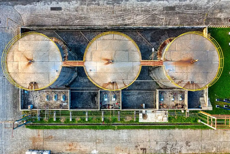
The DAF advantage is conditional — the unit only delivers the 92-97% TSS and 95% FOG numbers if four guardrails stay in range. First, pH must hold between 6.5 and 8.5; outside that window the polymer charge de-bonds and the floc will not carry the bubbles. Second, saturation pressure must stay at 4-6 bar; drop below 4 bar and bubble count collapses, push above 6 bar and the dissolution tank starts to waste energy without producing more nuclei. Third, the recycle ratio must sit between 10% and 30% — too low and there are not enough bubbles to lift the load, too high and the resulting turbulence shears the floc and the float drops back into the cell. Fourth, the skimmer blades need a weekly visual inspection; a dragging or misaligned blade is the single most common reason a DAF that tested perfectly at commissioning underperforms six months later.
Downstream of the DAF, a plate-frame filter press pushes the 3-5% float to 25-35% cake solids, reaching 98% total solids removal (HydropureWater field data, 2025) and shrinking the hauling line further. Every percentage point of additional float dryness compounds the $40,000/yr disposal savings from the ROI table, so dewatering is not an optional add-on — it is the step that locks in the payback window.
Frequently Asked Questions
When does a DAF clarifier beat a conventional clarifier on oily wastewater?
Whenever the stream carries free or emulsified oil, FOG, or fine suspended solids with specific gravity near or below 1.0. DAF hits 92-97% TSS and up to 95% FOG on a footprint 20-25% the size of a clarifier, while a clarifier typically delivers 40-60% TSS and under 30% FOG on the same stream because oil floats instead of settling.
What ROI can a Senatobia plant realistically expect from a DAF installation in 2026?
For a 50 m³/h stream in the $120,000-$180,000 CAPEX band, the combination of 0.2-0.5 kWh/m³ energy, 0.5-5 mg/L polymer, and 50-70% lower sludge hauling (from 3-5% float vs 1-2% clarifier underflow) typically returns the investment in 1.5-3 years, per the Hydropure 2025 framework.
How does DAF sludge need to be handled versus clarifier sludge?
DAF float leaves the cell at 3-5% solids and can be sent directly to a plate-frame filter press for dewatering to 25-35% cake solids, which cuts hauling volume and cost. Clarifier underflow at 1-2% solids usually needs a thickener step before dewatering and produces more total volume to haul off-site.
Can a conventional clarifier be retained as a polish step after a DAF?
Yes, and it is a common configuration for plants that already own a clarifier. The DAF takes the bulk oil and FOG load down to near-spec levels, and the clarifier catches any residual TSS as a low-cost polishing buffer before discharge — but the order cannot be reversed, because a clarifier in front of a DAF cannot drop the oil that the DAF is supposed to float.