Why Midstream Wastewater Is a Distinct Treatment Challenge
Shell treats wastewater at midstream facilities through a staged train: rotary bar screens and equalization remove coarse solids; dissolved air flotation (DAF) strips 90–95% of oil, grease, and suspended solids; biological treatment (MBR or activated sludge) reduces COD below 50 mg/L; reverse osmosis and selective desalination polish the stream; and zero-liquid-discharge (ZLD) crystallizers handle the brine concentrate. The system targets freshwater withdrawal intensity below 50 m³/tonne of hydrocarbon produced in water-stressed regions.
Midstream assets — gathering networks, processing plants, terminals, and storage tank farms — generate a wastewater profile that does not match refinery or upstream streams. The principal sources are flowback water (the first 2–4 weeks of fluid returning after a hydraulic-fracturing job), steady-state produced water (0.1–10× the hydrocarbon volume depending on basin and well age), hydrostatic test water, equipment wash-down, and rainwater runoff from tank-farm containment. In a typical Permian or Eagle Ford operation, total dissolved solids (TDS) lands between 50,000 and 250,000 mg/L, oil and grease (O&G) runs 100–1,000+ mg/L, total suspended solids (TSS) frequently exceed 500 mg/L, and scaling ions (Ca²⁺, Ba²⁺, Sr²⁺) plus naturally occurring radioactive material (NORM) introduce a handling hazard. A simple gravity clarifier cannot meet these loads — the oil droplets are too small, the TDS swing too wide, and the disposal pathway too regulated.
Fadhil's 2019 stochastic-optimization framework (Sustainability 11(18), 4865) formalized what operators had already been doing empirically: design shale-gas and oil wastewater systems as multi-stage trains that can absorb stochastic influent swings and switch between renewable and fossil power sources. That framework is now the baseline for specifying midstream water treatment. On top of that baseline sits Shell's operator-level freshwater intensity target — below 50 m³/tonne of hydrocarbon in water-stressed regions (per Shell's 2024 Water Position, as cited in industry ESG reporting, 2025-03) — which forces a higher recovery rate than a regulatory minimum. Inlet screening and equalization are the first line of defense; the upstream rotary mechanical bar screen typically protects the train at the head of the facility.
Step 1 — Headworks and Equalization at the Inlet
Rotary mechanical bar screens running in continuous duty open the train with aperture sizes of 3–10 mm, removing rags, plastics, frac sand carryover, and other coarse debris that would jam a DAF recycle pump or shred a biological reactor's mixers. Influent enters a covered equalization basin immediately downstream; hydraulic retention time (HRT) of 12–24 hours dampens the flow swings typical of flowback-to-produced-water transitions, where daily volumetric load can vary by a factor of three or more. Equalization also smooths the O&G and TDS load so that the chemical-conditioning dose ahead of DAF stays in spec, and so the biological reactor downstream sees a near-constant food-to-microorganism ratio.
From the equalization basin, the stream passes through an API, CPI, or corrugated-plate interceptor (CPI) for bulk free-oil removal. Design surface loading is typically held at or below 0.5 m/h to allow free oil to coalesce and rise without re-entraining. Skimmed free oil returns to a slop-oil tank for reclaim; the water phase then moves to the DAF stage. The combination of screening, equalization, and primary oil/water separation is what makes the downstream DAF and biological units operable at all — without it, a DAF unit sees slug loads that no micro-bubble system can ride through.
Step 2 — Dissolved Air Flotation for Oil, Grease and TSS Removal
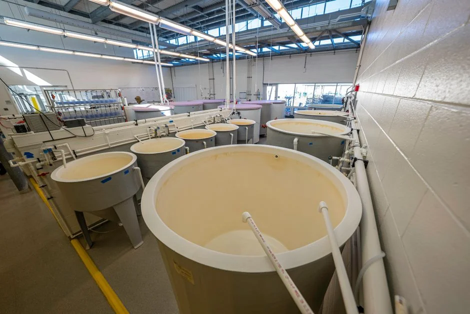
A DAF unit is the workhorse of the midstream pre-treatment stage because it strips emulsified oil and fine suspended solids that gravity separation cannot touch. Saturated recycle water at 4–6 bar releases micro-bubbles (typically 10–80 µm) when depressurized through the nozzle bank; the bubbles attach to oil droplets and floc particles, lifting them to the surface as a float layer that is skimmed into a sludge hopper. The performance envelope is well documented: 90–95% O&G removal, 80–90% TSS removal, plus a measurable reduction in colloidal matter (HydropureWater field data, 2026). Standard midstream DAF units span 4–300 m³/h, which covers the throughput range of virtually every satellite gathering plant and most central processing facilities in the Permian, Bakken, and Eagle Ford.
Chemical conditioning is essential in oil & gas service. A coagulant (typically ferric chloride, polyaluminum chloride, or a cationic emulsion breaker at 20–80 mg/L) neutralizes the charge on emulsified oil droplets, followed by an anionic or non-ionic flocculant (0.5–3 mg/L) that bridges the destabilized droplets into a strong, floatable floc. The automatic chemical dosing system upstream of the DAF handles the metering, dilution, and dose-tied-to-flow control that keeps performance stable across influent swings. The DAF effluent carries the bulk of the remaining COD load — usually 200–600 mg/L — but is now clean enough to feed either a biological reactor or a membrane unit without rapid fouling. A typical DAF unit for oil & grease removal in this service is sized to handle the full flow with 15–25% recycle ratio, which sets the saturated-water recirculation pump duty.
| Parameter | Typical Range (Oil & Gas Service) | Source |
|---|---|---|
| O&G removal | 90–95% | HydropureWater field data, 2026 |
| TSS removal | 80–90% | HydropureWater field data, 2026 |
| Saturated recycle pressure | 4–6 bar | Standard DAF design |
| Recycle ratio | 15–25% | Standard DAF design |
| Hydraulic capacity per unit | 4–300 m³/h | HydropureWater catalog, 2026 |
| Coagulant dose | 20–80 mg/L | Site-specific jar testing |
| Flocculant dose | 0.5–3 mg/L | Site-specific jar testing |
Step 3 — Biological Treatment: Conventional Activated Sludge vs. MBR
Biological treatment is where the dissolved and emulsified organics that survived DAF are mineralized. Two configurations dominate midstream service: conventional activated sludge (CAS) in an extended-aeration basin, and the membrane bioreactor (MBR) intensification of the same concept. CAS runs at HRT 18–36 hours and MLSS 3,000–5,000 mg/L, producing a clarified effluent with COD typically 80–150 mg/L and TSS 20–50 mg/L — adequate for surface discharge where permitted, but marginal for direct RO feed without further solids polishing. The CAS footprint is the limiting factor at sites where the tank farm sits inside a bermed lease pad with limited expansion room.
The MBR couples the activated-sludge basin to a submerged membrane module that physically retains the mixed liquor at <1 µm pore size, eliminating the secondary clarifier and delivering a much sharper effluent. Operating parameters shift accordingly: MLSS rises to 8,000–12,000 mg/L, HRT drops to 6–12 hours, and the overall reactor footprint shrinks by roughly 60% versus CAS at the same treatment load. Effluent quality is COD <50 mg/L, TSS <1 mg/L — directly suitable for RO feed. The trade-off is membrane cost, aeration energy, and periodic chemical clean-in-place cycles. Flat-sheet PVDF modules operate at 0.1 µm with 10–20× lower energy than external cross-flow hollow-fibre configurations (per Fadhil 2019 design baselines); the DF-series MBR module is the standard flat-sheet geometry used in this duty. For greenfield satellite sites of 1–80 m³/h, a packaged WSZ underground integrated sewage treatment unit combines screening, biological, and disinfection in a single buried skid, eliminating above-grade concrete and accelerating commissioning. A full skid-mounted MBR biological treatment system handles 10–2,000 m³/day and is the most common configuration for central midstream processing facilities. For a deeper dive on the membrane-side sizing math, see the 2026 spec guide on How to Size MBR for Compressor Oily Condensate (2026 Specs).
| Parameter | Conventional Activated Sludge (CAS) | Membrane Bioreactor (MBR) |
|---|---|---|
| HRT | 18–36 h | 6–12 h |
| MLSS | 3,000–5,000 mg/L | 8,000–12,000 mg/L |
| Effluent COD | 80–150 mg/L | <50 mg/L |
| Effluent TSS | 20–50 mg/L | <1 mg/L |
| Footprint (relative) | 1.0× | ~0.4× (≈60% smaller) |
| Membrane pore size | N/A | <1 µm (flat sheet 0.1 µm) |
| Typical use | Surface discharge, low reuse demand | RO feed, reuse for frac or cooling |
Step 4 — Membrane Polishing, RO and ZLD for Reuse or Brine Minimization
For any reuse target — hydraulic-fracturing source water, cooling-tower makeup, or steam-generation feed — the MBR effluent is run through a multimedia filter to bring the silt density index (SDI) below 3 before entering reverse osmosis. The multimedia filter (graded sand, anthracite, garnet, and optionally activated carbon) removes the residual particulates that would otherwise foul the RO spacers in days. The downstream industrial RO system then operates at up to 95% recovery, rejecting monovalent ions (Na⁺, Cl⁻) and divalent scaling ions (Ca²⁺, SO₄²⁻) to a concentrate stream roughly 4–5× the feed concentration. PLC-controlled operation with conductivity, ORP, and differential-pressure interlocks allows unattended duty — a critical feature for unmanned midstream sites.
ZLD extends the train with a brine concentrator (mechanical vapor recompression or thermal) and a crystallizer that converts the RO concentrate into a solid cake for landfill or road-base reuse, with the condensate recycled upstream. The CAPEX case for ZLD becomes compelling when deep-well injection permits are denied, surface-discharge TDS limits are tightening, or the operator's freshwater intensity target falls below 50 m³/tonne in a water-stressed basin — all common conditions in 2026. Fadhil (2019) also notes that the energy mix powering RO and crystallizer duty shifts the OPEX calculus, and operators increasingly co-locate solar or wind generation to stabilize the OPEX of the high-pressure pumps and thermal stages. For a broader market view of why reuse economics now favor RO and ZLD in oil & gas, see Water Reuse Growth Rate 2026: Industrial Market Data & Drivers.
Sludge Handling and Disinfection: The Two Sides Nobody Designs First
The residuals streams — DAF float and waste activated sludge — are typically dewatered with a plate-and-frame filter press in midstream service. Plate-and-frame units in the 1–500 m² filtration-area range deliver a 20–30% dry-solids cake that is suitable for landfill disposal, road base, or thermal destruction depending on NORM content. The dewatering supernatant returns to the head of the plant; a high-rate lamella clarifier at 20–40 m/h surface loading provides final polishing on the supernatant stream and protects the DAF and biological stages from recycle spikes.
Disinfection closes the aqueous loop. Chlorine dioxide generation is the standard for oil & gas service because the residual is controllable, biofilm formation is suppressed, and the reagent does not form trihalomethanes at the elevated bromide and TOC typical of midstream water. The ClO₂ generator on the treated-effluent line provides the required dose without the bulk-liquid storage hazard of hypochlorite. The full DAF float and dewatering line is typically handled by a plate-and-frame filter press, with a high-efficiency sedimentation tank polishing the supernatant before it rejoins the head of the plant.
Choosing the Right Train for a 2026 Midstream Project
The decision framework for a 2026 midstream build or revamp is driven by three variables: influent composition, reuse or discharge target, and the regulatory regime of the basin. Flowback-dominated sites with a demand for hydraulic-fracturing source water justify the full DAF + MBR + RO train, with ZLD added only when brine disposal cost exceeds crystallizer OPEX. Brackish produced water with permitted deep-well injection can stop at DAF + MBR, which meets surface-discharge limits and reclaims up to 80% of the water for cooling-tower or equipment-wash reuse. Water-stressed regions with zero-discharge ESG targets — including any site where Shell's freshwater intensity target of below 50 m³/tonne is binding — require the full DAF + MBR + RO + crystallizer train.
Capacity and footprint drive equipment selection inside each decision. Packaged A/O biological units (WSZ series) suit 1–80 m³/h satellite sites where above-grade construction is constrained. Containerized MBRs cover 10–2,000 m³/day for central processing facilities, and are the workhorse of the 2026 midstream buildout. Full ZLD is only justified above ~500 m³/day because the thermal stage's economy of scale requires a minimum brine throughput. Fadhil (2019) demonstrated that the OPEX penalty of grid electricity at the high-pressure pump and crystallizer can be offset by co-located renewable generation — a configuration that is now standard in new Permian and Eagle Ford builds. The operator's pre-design checklist should run, in order: influent characterization → discharge target → reuse demand → regulatory regime → energy budget → footprint constraint. The micro-bubble physics and recycle-ratios that govern the DAF core of every one of these trains are detailed in How Does a DAF Clarifier Work? Industrial Process Flow, Micro-Bubble Physics & 95%+ TSS Removal Explained.
| Scenario | Train Configuration | Typical Throughput | Trigger Condition |
|---|---|---|---|
| Flowback reuse for fracturing | DAF + MBR + RO | 10–2,000 m³/day | Active frac program with reuse demand |
| Brackish produced water, injection permitted | DAF + MBR | 1–80 m³/h (packaged) or larger | Deep-well-injection permit in good standing |
| Water-stressed, zero-discharge target | DAF + MBR + RO + crystallizer | >500 m³/day | Freshwater intensity <50 m³/tonne target, ZLD mandate |
| Satellite gathering site, surface discharge only | Screening + DAF + packaged biological | 1–80 m³/h | Remote site, limited footprint, surface discharge permitted |
Frequently Asked Questions
What is the first step in treating produced water at a Shell midstream plant?
Rotary bar screening removes coarse debris, followed by equalization (12–24 h HRT) and primary oil/water separation in an API or CPI unit. Only then does the stream move to DAF and biological treatment.
Why is DAF used before biological treatment?
DAF removes 90–95% of oil & grease and 80–90% of TSS, dropping the load on the biological reactor enough to prevent fouling and protect downstream RO membranes from rapid scaling.
Can midstream wastewater be reused for hydraulic fracturing?
Yes. DAF + MBR + RO polishing typically brings TDS, hardness, and O&G within fracturing-fluid specification, with RO recovery up to 95%.
When does a midstream facility need ZLD?
When deep-well injection is restricted, surface-discharge TDS limits are tightening, or operators target freshwater intensity below 50 m³/tonne in water-stressed regions — all common conditions in 2026.
How much smaller is an MBR versus a conventional activated-sludge plant?
Roughly 60% smaller footprint, with MLSS 8,000–12,000 mg/L and effluent COD under 50 mg/L.