Why DAF Clarifiers Outperform Sedimentation for Industrial Wastewater
Dissolved air flotation (DAF) systems achieve 92-97% TSS removal at influent concentrations of 200-500 mg/L, significantly outperforming conventional sedimentation tanks which typically reach only 60-80% efficiency for the same wastewater streams. This performance gap is primarily due to the density of the pollutants being treated. Gravity-based sedimentation relies on the settling velocity of particles heavier than water, typically those with a density greater than 1.2 g/cm³. However, many industrial wastewater streams—particularly in food processing, pulp and paper, and textile manufacturing—contain high concentrations of fats, oils, and grease (FOG) and biological flocs with densities ranging from 0.9 to 1.1 g/cm³. These low-density solids settle slowly or tend to float, making sedimentation an inefficient choice.
Beyond removal efficiency, DAF technology offers a drastic reduction in physical footprint. While a traditional sedimentation basin requires significant retention time to allow for gravity settling, a high-rate DAF system for industrial wastewater operates with a much shallower tank depth—often only 18 to 22 inches in circular "shallow air" configurations. This allows DAF units to require 50-70% less space than sedimentation tanks of equivalent capacity. For facilities with limited land or those requiring fiber recovery in paper mills, the ability to concentrate solids into a thick "float" layer (typically 2-6% solids) provides an immediate advantage for sludge handling and resource recovery.
| Parameter | DAF Clarifier | Sedimentation Tank |
|---|---|---|
| Target Particle Density | 0.9 – 1.1 g/cm³ (Floating/Neutral) | > 1.2 g/cm³ (Sinking) |
| TSS Removal Efficiency | 92% – 97% | 60% – 80% |
| FOG Removal Efficiency | 95% – 99% | < 50% (without skimmers) |
| Retention Time | 20 – 30 minutes | 2 – 4 hours |
| Footprint Required | Low (30-50% of sedimentation) | High |
The 4-Step DAF Process: From Chemical Conditioning to Float Skimming
The operational cycle of a DAF clarifier begins with chemical conditioning to transform emulsified and colloidal pollutants into buoyant, stable flocs. In Step 1, coagulants such as Polyaluminum Chloride (PAC) are dosed at 50-150 mg/L to neutralize the negative surface charges of suspended particles, followed by the injection of flocculants like anionic Polyacrylamide (PAM) at 1-3 mg/L. This process, often managed via PLC-controlled chemical dosing for DAF optimization, ensures that particles bridge together into larger aggregates. Maintaining a pH between 6.5 and 8.5 is critical; outside this range, the solubility of coagulants increases, leading to "pin floc" that escapes the flotation zone.
Step 2 involves the air saturation loop, which is the heart of the DAF process. A portion of the treated effluent (10-30% recycle ratio) is diverted to a saturation vessel where air is dissolved into the water at pressures of 4-6 bar (60-90 psi). According to Henry’s Law, the solubility of air in water is directly proportional to the partial pressure. In Step 3, this pressurized recycle stream is reintroduced to the main influent at the contact zone. As the pressure drops to atmospheric levels, the air precipitates out of solution, creating millions of micro-bubbles (20-50 µm). These bubbles nucleate on the surface of the chemical flocs through hydrophobic interactions, effectively reducing the overall density of the floc-bubble aggregate to less than that of water.
Finally, in Step 4, the floc-bubble aggregates rise to the surface at velocities of 0.1-0.3 m/min, forming a stable float layer. This layer, which can reach thicknesses of 5-15 cm, is removed by a mechanical skimmer—either a rotating paddle or a traveling bridge. The clarified water (subnatant) is drawn off from the bottom of the tank through a series of lateral pipes. To understand how the chemical stage integrates with the mechanical system, engineers often review how PAM dosing systems optimize DAF flocculation to ensure the float layer is robust enough to withstand the mechanical shearing of the skimmer blades.
Micro-Bubble Physics: How Bubble Size and Pressure Dictate DAF Efficiency
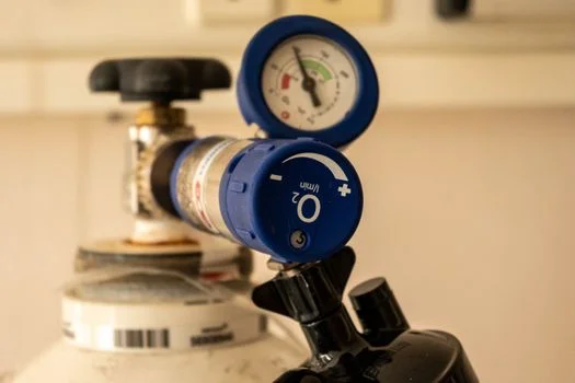
Micro-bubble generation in a DAF system is governed by the physics of nucleation and the pressure differential between the saturation tank and the flotation cell. The ideal bubble size for industrial wastewater treatment is 20-50 µm; bubbles larger than 100 µm (macro-bubbles) rise too quickly, creating turbulence that shears fragile flocs rather than lifting them. The relationship between bubble diameter and pressure is defined by the formula d_b = 2σ / ΔP, where σ represents the surface tension and ΔP is the pressure drop. By maintaining a saturation pressure of 4-6 bar, the system ensures a high density of nucleation sites, providing maximum surface area for floc attachment.
The recycle ratio is the primary lever for controlling bubble density. A standard rule of thumb is to provide 0.01 m³ of air per m³ of wastewater to achieve 95% TSS removal. If the recycle ratio is too low, there are insufficient bubbles to lift the solids load, leading to "sinking sludge" and high effluent TSS. Conversely, a recycle ratio exceeding 30% can lead to hydraulic overloading of the flotation tank and unnecessary energy consumption. Temperature also plays a significant role; in colder climates (10-15°C), air solubility increases, but the kinetics of chemical flocculation slow down. This requires operators to increase retention times or adjust polymer chemistry to compensate for the higher viscosity of the water (HydropureWater field data, 2025).
| Feature | Micro-Bubbles (DAF) | Macro-Bubbles (Aeration) |
|---|---|---|
| Size Range | 20 – 50 µm | 2 – 10 mm |
| Rise Velocity | 0.1 – 0.3 m/min | 10 – 20 m/min |
| Surface Area to Volume Ratio | Extremely High | Low |
| Primary Function | Particle Attachment & Lifting | Oxygen Transfer/Mixing |
| Pressure Requirement | 4 – 6 bar | < 1 bar (Blower pressure) |
DAF Performance Under Real-World Conditions: TSS, FOG, and COD Removal Data
In real-world industrial applications, DAF performance is measured by its ability to handle fluctuating influent loads while maintaining strict effluent standards for discharge or reuse. For food processing facilities dealing with high FOG loads, DAF systems consistently achieve 95-99% removal of oils and grease, even when influent concentrations exceed 1,000 mg/L. It is important to note that while DAF is highly effective at removing particulate Chemical Oxygen Demand (COD), it is less effective for soluble COD, such as sugars or alcohols. Typically, 85-95% of particulate COD is removed, while soluble COD removal is limited to 10-20% unless specialized adsorbents are used during the chemical conditioning phase.
The hydraulic loading rate (HLR) is the critical engineering parameter for sizing a DAF unit. Standard systems operate at 5-15 m/h (2-6 gpm/ft²), while high-rate circular units can reach up to 20 m/h. The required tank area (A) is calculated using the formula A = Q / HLR, where Q is the total flow rate (including recycle). For high-clarity requirements, such as post-DAF disinfection for reuse-quality effluent, operators often target the lower end of the HLR range to maximize retention time and ensure that even the smallest colloidal particles are captured by the micro-bubble cloud.
| Contaminant | Influent Concentration | Removal Efficiency (%) | Effluent Concentration |
|---|---|---|---|
| Total Suspended Solids (TSS) | 300 mg/L | 94% – 97% | < 20 mg/L |
| Fats, Oils, Grease (FOG) | 500 mg/L | 95% – 99% | < 10 mg/L |
| Particulate COD | 1,200 mg/L | 85% – 92% | < 150 mg/L |
| Total Phosphorus (TP) | 15 mg/L | 80% – 90% (with Alum) | < 2 mg/L |
DAF vs. Sedimentation: When to Choose Which (Decision Framework)
Choosing between a DAF clarifier and a sedimentation tank requires an analysis of particle settling velocity versus rise velocity. If the majority of the solids in the wastewater stream have a specific gravity significantly higher than 1.2 (e.g., sand, grit, or heavy metal precipitates), a high-efficiency sedimentation tank is the more cost-effective and operationally simple choice. However, if the stream contains emulsified oils, biological flocs, or fibers, DAF is the technically superior option. DAF also offers a chemical advantage; due to the high surface area of micro-bubbles, these systems often require 20-30% less coagulant and flocculant compared to sedimentation units to achieve the same clarity levels.
Space and sludge management also weigh heavily in the decision framework. Because DAF produces a thicker sludge (up to 6% solids) compared to the 1-2% solids typically found in sedimentation underflow, the costs associated with sludge dewatering and disposal are significantly reduced. While DAF systems involve more mechanical components—such as air compressors, saturation vessels, and recycle pumps—the maintenance overhead is often offset by the smaller footprint and higher effluent quality. For municipal applications involving algae removal or secondary clarification of activated sludge, DAF has become the standard due to its ability to handle "bulking sludge" that would otherwise fail to settle in a gravity clarifier.
| Decision Factor | Choose DAF If... | Choose Sedimentation If... |
|---|---|---|
| Primary Pollutant | FOG, Algae, Light Flocs | Grit, Sand, Heavy Metals |
| Space Availability | Very Limited / Indoor | Ample / Outdoor |
| Sludge Handling | High concentration preferred | Large volume handling okay |
| Chemical Budget | Optimization is prioritized | Standard dosages acceptable |
| Influent TSS | < 2,000 mg/L | Can handle > 5,000 mg/L |
5 Common DAF Operational Problems and How to Fix Them
Effective DAF operation requires balancing hydraulic flow, air saturation, and chemical dosing. When these parameters drift, performance degrades rapidly. Below are the five most common issues encountered by plant operators and their engineering solutions.
- Problem 1: Poor Float Layer Formation – This is usually caused by an insufficient air-to-solids ratio or weak floc structure. Fix: Increase the recycle ratio to 20-30% to provide more bubbles, and verify that the polymer dosage is sufficient to create robust flocs.
- Problem 2: Bubble Coalescence – If micro-bubbles merge into large bubbles, they lose their lifting power. This is often caused by saturation pressures exceeding 6 bar or high turbulence in the contact zone. Fix: Reduce saturation pressure to 4-5 bar and inspect the pressure release valves for wear or clogging.
- Problem 3: Float Layer Instability (Sinking Float) – If the float layer breaks apart and sinks, it is often due to pH fluctuations or temperature spikes. Fix: Use an PLC-controlled chemical dosing for DAF optimization to maintain a stable pH of 7.0-8.0 and check if influent cooling is required.
- Problem 4: High Effluent TSS – This typically indicates hydraulic overloading or "short-circuiting" where water bypasses the flotation zone. Fix: Check the hydraulic loading rate against design specs (max 15 m/h) and ensure the internal baffles are not damaged.
- Problem 5: Excessive Chemical Usage – Overdosing chemicals can be as detrimental as underdosing, leading to high operational costs and "slimy" sludge. Fix: Conduct regular jar testing to find the optimal dose and ensure the flocculation tank provides 2-5 minutes of gentle mixing time.
Frequently Asked Questions
What is the typical TSS removal efficiency of a DAF system? DAF systems typically achieve 92% to 97% TSS removal for influent concentrations between 50 and 500 mg/L. In high-load industrial applications like food processing, removal rates can exceed 98% when combined with optimal chemical conditioning.
How does bubble size affect DAF performance? The ideal bubble size is 20-50 µm. Bubbles in this range provide the maximum surface area for attachment to flocs. Bubbles larger than 100 µm rise too fast and create turbulence, while bubbles smaller than 10 µm may not provide enough buoyancy to lift heavy solids.
What is the ideal air-to-solids ratio for DAF? A standard air-to-solids (A/S) ratio for industrial DAF systems is 0.02 to 0.05 lb of air per lb of solids. This ratio ensures there is enough "bubble power" to lift the entire solids load to the surface without over-saturating the system.
Can DAF remove dissolved contaminants like sugar or salt? No, DAF is a physical separation process designed for suspended solids and emulsified oils. Dissolved contaminants like sugars (BOD) or salts (TDS) require biological treatment or membrane filtration (RO/UF) for effective removal.
How much space does a DAF system require compared to a clarifier? A DAF system typically requires only 30% to 50% of the footprint of a conventional gravity clarifier. This is due to the much higher loading rates (5-15 m/h for DAF vs 1-2 m/h for sedimentation) and shallower tank designs.
Related Equipment
- DAF systems for industrial wastewater — view specifications, capacity range, and technical data
- PLC-controlled chemical dosing for DAF optimization — view specifications, capacity range, and technical data
Need a customized solution? Request a free quote with your specific flow rate and pollutant parameters.