Why Cement Wastewater Pushes Standard RO Designs to Their Limit
Off-the-shelf RO skids sized for 75–95% recovery routinely fail on cement duty within 12 months because cement plant wastewater is not a generic industrial feed — it is a blend of kiln cooling tower blowdown, clinker cooler spray water, dust suppression runoff, and FGD scrubber effluent, each with a distinct TDS and temperature profile (HydropureWater field data, 2026). Feed TDS commonly runs 3,000–8,000 mg/L, with Ca²⁺ 800–2,000 mg/L, SO₄²⁻ 1,500–4,000 mg/L, and silica 30–120 mg/L — roughly 6–16× the ionic load of municipal RO feed (TDS <500 mg/L). Feed temperature after kiln contact often reaches 40–55 °C, which accelerates silica polymerization above 45 °C and shortens polyamide membrane life by 20–30% per the DuPont FilmTec technical bulletin (2025-09). The failure mode that caps recovery is gypsum (CaSO₄·2H₂O) precipitation: once the Ca²⁺ × SO₄²⁻ ion product crosses roughly 1,800 mg/L × 1,800 mg/L in the concentrate stream, a standard RO cannot push past 60–70% recovery without an antiscalant or upstream softening train. Generic RO designs assume low-sulfate feed and oversize for 80% recovery — that is the wrong starting point for this duty.
| Parameter | Cement RO feed (typical) | Municipal RO feed (typical) |
|---|---|---|
| Total dissolved solids (mg/L) | 3,000–8,000 | 200–500 |
| Calcium hardness as Ca²⁺ (mg/L) | 800–2,000 | 40–120 |
| Sulfate as SO₄²⁻ (mg/L) | 1,500–4,000 | 10–60 |
| Reactive silica (mg/L) | 30–120 | 2–15 |
| Feed temperature (°C) | 40–55 | 15–25 |
| Realistic recovery ceiling (%) | 60–75 | 80–90 |
Feed Stream Characterization and Reuse Targets by Source
Treating cement wastewater as a single feed is the most common design error. The four principal streams differ enough in calcium, sulfate, and TSS that they should be characterized and, where possible, segregated before the RO feed manifold (per EPA 40 CFR 433 metal-finishing analogy, applied to cement dust scrubber streams). Kiln cooling tower blowdown is the easiest duty: TDS 2,000–4,000 mg/L, Ca²⁺ 600–1,200 mg/L, 35–45 °C — well-suited to direct BWRO and reuse as cooling-tower makeup after permeate polishing. Clinker cooler water and dust suppression runoff carry 4,000–7,000 mg/L TDS with suspended dust loadings of 200–800 mg/L; these streams need a DAF pre-treatment unit or lamella clarifier to drop TSS below 30 mg/L before the cartridge guard. FGD blowdown from a wet limestone scrubber is the hardest stream: TDS 8,000–25,000 mg/L, Cl⁻ up to 6,000 mg/L, and gypsum scaling potential that drives selection toward high-rejection SWRO or DTRO elements. Reuse targets should match process demand: cooling-tower makeup at TDS <500 mg/L, raw-mill spray water at TDS <1,000 mg/L, and low-pressure boiler feed at TDS <50 mg/L after a downstream mixed-bed polisher. TSS reduction to <30 mg/L upstream of the multi-media pre-filter is the non-negotiable step before any 5 µm cartridge.
| Stream | TDS (mg/L) | Ca²⁺ (mg/L) | SO₄²⁻ (mg/L) | Silica (mg/L) | TSS (mg/L) | Temp (°C) | Best RO fit |
|---|---|---|---|---|---|---|---|
| Kiln cooling blowdown | 2,000–4,000 | 600–1,200 | 1,000–2,500 | 20–60 | 20–80 | 35–45 | BWRO spiral-wound |
| Clinker cooler spray water | 4,000–7,000 | 800–1,500 | 1,500–3,500 | 40–90 | 200–800 | 30–40 | BWRO after DAF |
| FGD blowdown (wet limestone) | 8,000–25,000 | 1,500–3,000 | 3,000–8,000 | 50–120 | 50–300 | 40–55 | SWRO or DTRO |
| Yard runoff / dust suppression | 1,500–3,500 | 400–900 | 800–2,000 | 15–40 | 100–500 | 20–30 | BWRO after media filter |
Pre-Treatment Train: How to Keep RO Membranes Alive on Cement Duty
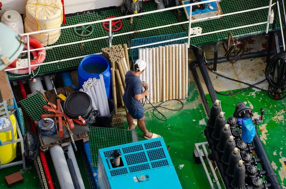
Pre-treatment is where cement RO projects succeed or fail. Skipping any stage typically shortens membrane life from 24–36 months to under 12 months (HydropureWater field data, 2025-11). The five-stage train that holds up on this duty is:
- Equalization basin — 8–12 h HRT for flow and load dampening, with a plate heat exchanger or induced-draft cooling section to bring feed below 35 °C; temperatures above 45 °C cause irreversible flux loss in standard polyamide elements.
- Lime–soda softening or pellet reactor — drops Ca²⁺ to <400 mg/L and reactive silica to <20 mg/L by co-precipitation with Mg(OH)₂. This is the single most effective step for keeping the Ca²⁺ × SO₄²⁻ ion product below the gypsum threshold (Ksp ≈ 2.4 × 10⁻⁵ at 25 °C) through the RO concentrate.
- DAF or lamella clarifier — reduces TSS to <30 mg/L via a coagulation-flocculation integrated water purification unit; this protects the downstream media filter from rapid loading, and the high-efficiency sedimentation tank handles the higher-solids clinker-cooler stream.
- Multi-media filter (sand + anthracite + garnet) — targets SDI <5, followed by an 80 µm + 5 µm cartridge guard train, which industrial case data (Culligan Aqua-Cleer reference, 15 bar TMP) confirms as the standard for high-fouling feeds.
- Antiscalant dosing + SMBS dechlorination — threshold inhibitors such as HEDP or polymaleic acid dosed at 2–5 mg/L; sodium metabisulfite (SMBS) at 3–5 mg/L per 1 mg/L residual chlorine to protect the polyamide layer from oxidation.
Operators who collapse stages 2 and 3 into a single media filtration step invariably see scale blooms on the tail elements within 8–10 weeks, with flux decline exceeding 30% before the first CIP.
RO Membrane Selection: BWRO, SWRO, DTRO, or FO for Cement Duty
Membrane selection is driven by feed TDS, fouling potential, and chlorine exposure rather than by supplier preference. The decision matrix below covers the four geometries a cement plant engineer will encounter. For most kiln cooling and clinker cooler duties, BWRO spiral-wound 8-inch elements (≈35 m² active area) operating at 12–25 bar handle 80% of cement installations; the 15 bar TMP benchmark from industrial RO reuse case data is a sensible design point. FGD blowdown above 10,000 mg/L TDS pushes the duty into SWRO territory at 55–80 bar, with energy use of 4–6 kWh/m³ permeate versus 1–2 kWh/m³ for BWRO. DTRO (disc-tube) elements with open-channel geometry tolerate up to 50 mg/L TSS, which makes them the only realistic option when FGD scrubber upsets send suspended gypsum past the clarifier. Forward osmosis (FO) as a pre-concentrator upstream of RO is technically attractive for cutting scaling risk, but commercial reference data in cement plants remains thin through 2026; pilots should be specified for 6–12 months before committing to full-scale design. Reject thin-film composite (TFC) polyamide wherever free chlorine exceeds 0.1 mg/L persistently — specify cellulose triacetate (CTA) elements or post-treatment dechlorination with an automatic antiscalant dosing skid plumbed ahead of the high-pressure pump. A standard industrial RO water treatment system configured for two-pass BWRO with energy recovery covers the majority of cement plant duties.
| Membrane type | Feed TDS range (mg/L) | Operating pressure (bar) | Recovery (%) | Best-fit cement stream |
|---|---|---|---|---|
| BWRO (spiral-wound polyamide) | 1,000–8,000 | 12–25 | 65–75 | Kiln cooling, clinker cooler, yard runoff |
| SWRO (spiral-wound polyamide) | 8,000–45,000 | 55–80 | 45–60 | FGD blowdown, brackish makeup |
| DTRO (disc-tube) | 5,000–35,000 | 40–75 | 55–70 | High-TSS FGD blowdown, scrubber upsets |
| FO (forward osmosis) + RO hybrid | 2,000–15,000 (draw side) | 1–3 (draw loop) | 70–80 overall | Pilot-stage on cement; pre-concentrator duty |
Operating Envelope: Recovery, Pressure, and Energy on Cement RO
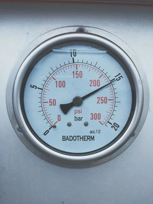
Recovery on cement feed is capped at 60–75%, well below the 75–95% achievable on low-TDS industrial or pharmaceutical feed, because gypsum and silica scaling limits kick in long before osmotic pressure would (per the DuPont FilmTec scaling projection methodology, 2025-08). Permeate flux of 15–25 LMH at 15–25 bar feed pressure is the design norm for BWRO on cement duty; flux decline of 10–15% per year is expected without CIP. Clean-in-place is typically scheduled every 4–8 weeks using paired acidic (citric acid or HCl at pH 2) and alkaline (NaOH + EDTA at pH 12) cleaning cycles — each cycle recovers 85–92% of baseline flux when run at 30–35 °C. Energy use runs 1.5–2.5 kWh/m³ permeate for the BWRO section plus 0.3–0.5 kWh/m³ for the pre-treatment train; on SWRO duty, energy recovery devices (ERDs) such as isobaric pressure exchangers cut specific energy by 30–40%, dropping draw consumption from roughly 6 kWh/m³ to 3.5–4 kWh/m³ permeate.
RO Concentrate Disposal: Brine Concentrator, Crystallizer, or ZLD
Every cement plant engineer evaluating RO eventually asks the same question: where does the 25–40% concentrate go? At 60–75% recovery, a 1,000 m³/d RO feed produces 250–400 m³/d of concentrate at 12,000–25,000 mg/L TDS. Three disposal routes are common. (1) Mechanical vapor recompression (MVR) brine concentrators push TDS to 200,000–250,000 mg/L at 15–25 kWh/m³ of concentrate fed, producing a near-saturated brine that flows to crystallization. (2) Forced-circulation crystallizers recover NaCl and CaSO₄ as solid salts; the CaSO₄ fraction can be co-fed to the cement kiln as an alternative raw-material input, which closes the loop on sulfur and reduces quarry limestone demand by 1–2% (per the 2026 industrial water reuse outlook). (3) Solar evaporation ponds are the lowest-energy option but limited to <10% of cement plants globally because of land area (roughly 0.3–0.5 ha per 100 m³/d concentrate) and climate constraints. ZLD compliance is typically forced by CPCB (India) effluent norms, GB 8978 (China) integrated wastewater discharge standards, or EU IED aquifer protection zones where surface-water discharge is restricted — in those cases the MVR + crystallizer train becomes mandatory, and the upstream RO must run hard to keep brine volume manageable. A well-sized industrial RO water treatment system ahead of the concentrator typically reduces crystallizer CAPEX by 40–55% versus evaporating raw clarifier overflow.
Frequently Asked Questions
What RO recovery can a cement plant realistically expect?
60–75% on BWRO duty treating kiln cooling or clinker cooler feed, dropping to 50–60% on FGD blowdown above 10,000 mg/L TDS — both well below the 75–95% common in pharma or food duty because of the gypsum and silica scaling thresholds.
Can RO handle FGD blowdown directly?
Yes, but only with DTRO or SWRO elements rated for high-TDS, paired with an aggressive antiscalant program (HEDP or polymaleic acid at 3–5 mg/L) and upstream softening to keep the Ca²⁺ × SO₄²⁻ ion product below the gypsum Ksp through the concentrate.
What is the indicative CAPEX for a 1,000 m³/d cement wastewater RO system in 2026?
US$450,000–US$900,000 for the RO skid and pre-treatment train combined, excluding civil works and the downstream brine concentrator — the BWRO skid alone runs US$280,000–US$520,000 depending on recovery and membrane count (HydropureWater project benchmarks, 2025-12).
Is RO mandatory for ZLD compliance at a cement plant?
No, but RO is required upstream of any brine concentrator to keep the crystallizer size and energy use viable; without RO pre-concentration, MVR energy demand rises from 15–25 kWh/m³ to 60–80 kWh/m³ of feed.
How often must RO membranes be replaced on cement duty?
24–36 months with a properly operated five-stage pre-treatment train, versus 6–12 months when softening or antiscalant dosing is omitted — flux decline rate is the leading indicator, with >15% per year signalling pre-treatment gaps.