Why Wafer Slicing Wastewater Is Harder Than It Looks
A single advanced PV or semiconductor fab consumes 2–4 million gallons of water per day (per VSEP industry data), and the wire-saw slicing loop is the single largest consumptive stream on site. Wafer slicing wastewater treatment targets the abrasive slurry stream from wire saws — typically silicon carbide (SiC) in polyethylene glycol (PEG) carrier — plus downstream cleaning effluent containing surfactants and organic acids. A modern train uses pre-settling for SiC recovery, chemical conditioning, dissolved air flotation or lamella clarification, and ultrafiltration or RO polishing, enabling 90% water reuse and sub-ppm suspended solids in the recycled loop.
The slurry itself is engineered for performance, not for easy separation. Solids load runs 5–15 wt% as a stable suspension of 50–300 nm SiC particles in PEG 200–400 carrier. That carrier fluid gives the mixture a viscosity of 80–200 cP at 25°C, which suppresses settling and pumps energy costs up. The colloids are surface-treated to resist aggregation during cutting, which is exactly the property that defeats conventional clarification downstream. They do not settle under gravity, they foul cross-flow membranes within minutes of operation, and they require deliberate destabilization chemistry before any solid-liquid separation stage will work.
Engineers specifying treatment must first identify which of the two slicing regimes their fab runs, because the waste streams are fundamentally different. Loose-abrasive slurry sawing — the legacy process — uses SiC grit suspended in PEG carrier at high solids. Diamond-wire saw (DWS) slicing, dominant in mono-crystalline PV production since ~2015, uses a water-based glycol coolant with only 0.5–3% silicon fines and no free abrasive. Treating the two streams with the same train is the most common specification error in this market and produces overloaded clarifiers or under-loaded membrane systems on day one.
Loose-Abrasive Slurry vs Diamond-Wire Saw Wastewater: Side-by-Side
The selection mistake the industry keeps making is assuming both streams can ride the same pre-treatment. They cannot. Loose-abrasive slurry is a viscous, high-solids fluid that demands bulk separation before any chemistry is added; diamond-wire saw coolant is dilute enough for chemical conditioning and flotation from the start. The comparison below is the rule of thumb for choosing the front end of the train.
| Parameter | Loose-Abrasive (SiC + PEG) | Diamond-Wire Saw (DWS) |
|---|---|---|
| Solids content | 5–15 wt% SiC | 0.5–3% silicon fines |
| Carrier fluid | PEG 200–400 (viscous, 80–200 cP) | Water + glycol coolant (1–5 cP) |
| Dominant contaminant | SiC grit, PEG, trace metal | Silicon fines, surfactant, organic acid |
| Typical COD | 10,000–30,000 mg/L | 2,000–8,000 mg/L |
| Particle size | 5–20 µm SiC | 0.5–5 µm Si fines |
| Target reuse | 85–90% (recovered SiC + RO loop) | 90–95% (UF + RO loop) |
| Recommended pre-treatment | Decanter centrifuge → sedimentation → chemistry | Coagulation/flocculation → DAF or lamella |
The decision rule is simple: if the stream is a high-solids viscous slurry, route it to a decanter centrifuge or settling tank first to recover abrasive and drop the solids load by 70–85% before any chemical stage. PEG carries too much COD for direct biological treatment, and the high viscosity starves DAF of the bubble-rise time it needs. If the stream is a dilute coolant with sub-3% fines, skip the centrifuge and dose coagulant directly into a DAF system for colloidal silicon removal or lamella clarifier for SiC slurry polishing. This single front-end choice determines the rest of the equipment list.
The 2026 Process Train: From Cutting Table to Reuse Loop
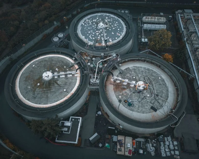
The end-to-end train for wafer slicing wastewater in 2026 runs five stages, each with measurable design parameters. This is the configuration most PV wafer fabs in China and Southeast Asia now specify for new builds, and it is also the upgrade path for legacy plants moving from once-through discharge to closed-loop reuse.
| Stage | Equipment | Design Parameter | Performance Target |
|---|---|---|---|
| 1. Primary SiC/silicon recovery | Settling tank or decanter centrifuge (3,000–4,000 G) | HRT 2–4 h (settler); 15–30 min (centrifuge) | 70–85% SiC capture; recovered abrasive returned to slurry make-up |
| 2. Chemical conditioning | Automatic chemical dosing for coagulation with PAC + anionic flocculant | pH 7–8.5; PAC 50–200 mg/L; flocculant 0.5–2 mg/L | Colloid destabilization; zeta potential near 0 mV |
| 3. Solid-liquid separation | DAF (low TSS) or lamella clarifier (higher loadings) | DAF HRT 20–30 min; lamella surface loading 5–10 m³/m²·h | TSS <50 mg/L downstream |
| 4. Polishing | Multi-media filter + UF | MMF 10–15 m/h; UF 0.01–0.1 µm at 40–80 LMH, 0.2 MPa | Turbidity <1 NTU; SDI <3 for RO feed |
| 5. Closed-loop reuse | Industrial RO system for closed-loop reuse (single or two-pass) | RO recovery 70–85%; flux 15–25 LMH | Conductivity <10 µS/cm; concentrate to crystallization or evaporation |
Stage 1 is where SiC pays back. A decanter centrifuge running at 3,000–4,000 G captures 70–85% of the abrasive in a washable cake that can be returned to slurry make-up, displacing 15–25% of fresh SiC purchase. In a 500 m³/h fab, that is meaningful tonnage per month.
Stage 2 uses polyaluminum chloride (PAC) at 50–200 mg/L paired with an anionic flocculant at 0.5–2 mg/L to neutralize the surface charge that keeps the colloids in suspension. Without this step, no downstream clarifier or membrane will perform to spec.
Stage 3 selection depends on the influent. DAF handles low-TSS streams (under ~500 mg/L after centrifuge) with rapid rise rates; lamella clarifiers handle higher loadings on a smaller footprint. Effluent TSS should drop below 50 mg/L before polishing.
Stage 4 protects the RO. A multi-media filter for polishing drops bulk solids, then a 0.01–0.1 µm UF brings turbidity under 1 NTU and the silt density index (SDI) under 3, which is the working ceiling for spiral-wound RO membranes.
Stage 5 is the reuse loop. RO recovery of 70–85% produces permeate suitable for non-UPW process water (cooling tower makeup, saw machine rinse, final cleaning pre-rinse). Concentrate goes to a crystallization or mechanical vapor recompression (MVR) evaporator for zero-liquid-discharge (ZLD) sites, or to a smaller side-stream RO that recovers another 50% before brine disposal. Sludge from the lamella underflow is dewatered with a filter press for SiC sludge at 25–35% dry solids for off-site disposal or landfill.
Process Parameters and Performance Benchmarks
These are the numbers an engineer uses to size equipment, write a specification, and validate vendor bids. The performance benchmarks reflect a properly operated full train (settler/centrifuge + chemistry + DAF/lamella + UF + RO), not single-stage results (HydropureWater field data, 2026).
| Parameter | Raw Influent | Post-DAF/Lamella | Post-UF | Post-RO (Reuse) |
|---|---|---|---|---|
| TSS (mg/L) | 5,000–15,000 | <50 | <2 | <1 |
| Turbidity (NTU) | >10,000 | 10–30 | <1 | <0.5 |
| COD (mg/L) | 10,000–30,000 | 500–1,500 | 200–500 | <50 |
| BOD₅ (mg/L) | 6,000–20,000 | 300–900 | 100–300 | <20 |
| SiC residual (mg/L) | 5,000–12,000 | <30 | <5 | <1 |
| Conductivity (µS/cm) | 200–2,000 | 200–2,000 | 200–2,000 | <10 |
| pH | 5–9 | 7–8.5 | 7–8.5 | 6.5–7.5 |
TSS reduction across the full train is 99.9% (10,000 mg/L raw to under 10 mg/L polished). Turbidity falls from over 10,000 NTU in the raw slurry to under 0.5 NTU post-RO, which is the threshold for UPW-loop make-up. COD drops from 15,000 mg/L to under 50 mg/L; BOD₅ runs 60–70% of COD in slicing streams, which means biological polishing is rarely worth the footprint when RO is already on the line.
Membrane operating envelopes are tight. UF runs at 40–80 LMH at 0.2 MPa transmembrane pressure with backwash every 30–60 minutes; RO runs at 15–25 LMH at 1.0–1.5 MPa with chemical cleaning every 4–8 weeks. Exceeding these fluxes on slicing wastewater is the fastest way to foul a membrane stack. The integrated MBR system works for the downstream organic load from wafer cleaning but is the wrong primary stage for abrasive slurry — see the framework section for why.
Water Reuse Economics: 90% Recovery in Practice

Pall's silicon-processing reclamation systems routinely deliver 90% reuse of spent process water as high-quality feed (per Pall 2026 datasheet), and the same ratio is now standard for new PV wafer builds in China. The payback math defends itself when water is priced at industrial rates and DI makeup is the dominant cost driver.
| Variable | Low Case | High Case | Notes |
|---|---|---|---|
| Water cost (USD/m³) | 1.50 | 3.00 | Site-dependent; higher in water-stressed regions |
| Slicing-loop flow (m³/h) | 500 | 500 | ~50 MW mono wafer fab baseline |
| Reuse rate | 90% | 90% | UF + RO closed loop |
| Annual water recycled (million m³) | 3.6 | 3.6 | 500 × 24 × 330 × 0.90 / 1,000,000 |
| Annual water cost savings (USD) | 5.4M | 10.8M | At midpoint: ~7.2M USD/year |
| System CAPEX (USD, 2026) | 2.8M | 4.5M | Excludes civil works and ZLD evaporator |
| Payback on water alone (months) | 5 | 10 | Excludes SiC resale and DI savings |
Secondary savings push payback shorter. A 60–80% reduction in DI water makeup lowers both the DI regeneration cycle count and the resin replacement budget. Effluent surcharges in tier-1 Chinese cities now run 0.3–0.8 USD/m³ of discharge, so reducing blowdown by 3.6 million m³/year saves another 1.0–2.9M USD. Recovered SiC displaces 15–25% of fresh abrasive purchase, worth 200–500k USD/year at a 500 m³/h fab. A full discussion of these resource-recovery economics is in the resource recovery and ROI for industrial wastewater brief.
The wider market context — including the regulatory and capex backdrop for 2026 — is covered in the 2026 industrial wastewater market trends analysis. Fabs that have already closed the loop report 6–10 month payback on water savings alone, with ZLD configurations like the wafer fab fluoride and silica ZLD case study reaching fluoride residuals under 0.5 mg/L and silica under 1 mg/L for discharge or crystallizer feed.
Choosing Equipment: A 2026 Decision Framework
Vendor selection for slicing-water treatment should run on six criteria, in this order. Abrasive-handling capability is the first filter — if the proposed system was designed for municipal or food-processing effluent, it will not survive a SiC slurry.
- Abrasive handling: Decanter centrifuge must be rated for 5–15 wt% solids with hardened scroll; pumps must be slurry-rated (≥30% solids passing); pipework should be rubber-lined or HDPE for erosive service.
- Recovery target: Specify 70–85% SiC capture at the front end and 90% water reuse at the back end as separate contractual KPIs, not bundled.
- Footprint: Match equipment to flow regime: under 20 m³/h → packaged skid; 20–100 m³/h → modular containerized; over 100 m³/h → site-built concrete tanks with custom skids.
- Automation level: Inline TSS, turbidity, pH, and conductivity probes with automatic coagulant feedback. Manual dosing is the single biggest cause of off-spec RO feed in legacy fabs.
- After-sales support: Local service team with 48-hour response, spare membrane stock, and consumables (PAC, flocculant, cleaning chemicals) under vendor supply agreement.
- Lead time: 12–20 weeks for engineered skids in 2026; 30+ weeks for custom concrete clarifiers. Plan procurement against mechanical completion, not PO date.
Material of construction follows the stream. SS316L is the safe choice for any stream with chloride over 200 mg/L or for RO frames. PP or FRP suits dilute coolant service below 60°C. Rubber-lined carbon steel handles erosive SiC slurries at the lowest cost — it is the workhorse material for settling tanks, pump boxes, and slurry lines.
The procurement mistake that costs the most rework is specifying a domestic-style MBR package for the primary abrasive stream. MBRs are designed for municipal-strength organic loads (COD 300–800 mg/L) with mixed-liquor biology. Slicing wastewater at 15,000 mg/L COD with abrasive solids will shred the membrane fibers and overload the biomass. Save MBRs for the downstream wafer-cleaning effluent where they belong, and use a properly rated physical-chemical train for the slicing loop.
Compliance Snapshot: Slicing Effluent Limits in 2026
Regulatory limits are tightening, and the engineer should know which floor applies before the equipment list is finalized. The three jurisdictions below cover most of the global PV wafer and semiconductor fab footprint.
- China: GB 39728-2020 and GB 30485 (semiconductor industry effluent) require SS ≤10 mg/L, COD ≤30 mg/L, fluoride ≤1.5 mg/L, ammonia nitrogen ≤5 mg/L. Effluent to surface water bodies is tested at the discharge point.
- United States: EPA 40 CFR Part 469 (electrical and electronic components, semiconductor category) sets daily-max TSS at 30 mg/L and monthly-average fluoride at 4 mg/L, with reporting through the NPDES permit.
- European Union: The 2023 BREF update for semiconductors targets TOC ≤10 mg/L and TSS ≤5 mg/L for reuse loops. Local permitting may set stricter limits based on receiving water body.
Fabs exporting wafers to EU customers under CBAM-style traceability or supplier ESG audits may face contractually lower limits than the regulation requires, especially for fluoride and total heavy metals. Plan for a polishing stage (UF + RO) rather than relying on chemistry alone, because the regulatory floor is moving down faster than most legacy plants can respond.
Frequently Asked Questions
What contaminants dominate wafer slicing wastewater? Silicon carbide (SiC) abrasive, silicon fines from the kerf, PEG or glycol carrier fluid, and — from downstream cleaning — surfactants, lactic or citric acid, and trace metals. The COD load is carried almost entirely by the carrier fluid and the cleaning additives, not by the abrasive.
Can DAF alone treat slicing wastewater? No. The colloids are surface-stabilized to resist aggregation; DAF without coagulation will pass 70–90% of the solids through. The minimum train is coagulation with PAC plus anionic flocculant, followed by DAF or lamella, followed by media filtration or UF.
What reuse rate is realistic in 2026? 85–95% with a full UF + RO train, 70–80% with media filtration only. The 90% figure widely cited in industry literature is achievable in steady state but requires consistent influent and disciplined maintenance.
How is SiC recovered? Sedimentation or, more commonly, decanter centrifuge operating at 3,000–4,000 G. The underflow cake is washed to remove PEG residue and returned to slurry make-up, displacing 15–25% of fresh abrasive.
What is the difference between slicing wastewater and CMP wastewater? Slicing wastewater is SiC- and PEG-dominated, with high COD and abrasive solids. CMP wastewater is colloidal silica, alumina, or ceria with oxidizers (hydrogen peroxide, ammonium hydroxide) and a much lower COD. The two streams need separate treatment trains — applying the slicing train to CMP misses the oxidizer-destruction step, and applying the CMP train to slicing overloads the membrane stage with abrasive.