
Why Machining Coolant Blowdown Is Unusual Wastewater
Spent machining coolant blowdown typically exhibits a chemical oxygen demand (COD) concentration of 3,000 to 15,000 mg/L and a biochemical oxygen demand (BOD) to COD ratio of only 0.3 to 0.5 (source: HydropureWater engineering design manual, 2026). When determining how do you size MBBR for a factory discharging machining coolant blowdown, the chemical composition of the influent dictates every downstream hydraulic and biological volume calculation. Unlike municipal wastewater, machining coolant blowdown is heavily loaded with emulsified mineral or synthetic oils (200 to 2,000 mg/L), synthetic surfactants, and recalcitrant biocides such as triazines or isothiazolinones, all while operating at an alkaline pH of 8.0 to 10.0.
This high concentration of emulsified oil wastewater acts as a direct barrier to biological treatment. If introduced directly to a biological reactor, the oil droplets coat the suspended biomass or biofilm, preventing oxygen transfer and substrate diffusion, which ultimately collapses the treatment process. Consequently, physical pre-treatment is a strict requirement rather than an option. A moving bed biofilm reactor design is highly suitable for this application because its attached-growth biomass on protected plastic carriers is far more resilient to periodic surfactant slug loads and residual oil carryover than conventional suspended-growth activated sludge systems. recent academic research, such as a 2025 MDPI biological integration study (doi: 10.20944/preprints202512.0976.v1), positions MBBR alongside anaerobic-anoxic-oxic (A2O), UASB, SBR, and MBR systems as a premier biological option for handling high-strength industrial wastewaters containing complex organic matrices.
| Parameter | Machining Coolant Blowdown Range | Typical Municipal Wastewater | Process Sizing Impact |
|---|---|---|---|
| COD (mg/L) | 3,000 – 15,000 | 250 – 500 | Requires extended aeration and high biomass concentration |
| BOD/COD Ratio | 0.3 – 0.5 | 0.5 – 0.6 | Indicates slow biodegradation kinetics; requires lower design loading |
| Oil & Grease (mg/L) | 200 – 2,000 | 20 – 50 | Mandates high-efficiency upstream DAF separation to prevent carrier fouling |
| pH Range | 8.0 – 10.0 | 6.5 – 7.5 | Requires mineral acid neutralization prior to biological stages |
Step 1 — Characterize the Influent Before You Touch a Calculator
A 10-machine CNC cell operating three shifts typically generates between 5 and 30 m³/d of highly concentrated coolant blowdown and washwater (source: HydropureWater field data, 2026). Sizing a biological system on grab-sample data alone is a high-risk approach. To establish a defensible design basis, process engineers must collect 24-hour flow-proportional composite samples to capture the true mass loading of the facility. The seven critical parameters that must be logged before initiating calculations are daily flow rate (Q), total COD, BOD₅, oil and grease (O&G), total suspended solids (TSS), pH, and minimum operating temperature.
In metalworking plants, sump cleanouts are performed periodically, causing batch dumps that can spike influent COD and oil concentrations by 200% to 300% over baseline values. Without equalization, these spikes will overload the biological reactor, causing immediate biocarrier media washouts or biofilm suffocation. Therefore, a minimum of 24 hours of equalization volume must be designed upstream of the biological process to homogenize the wastewater and guarantee a stable mass loading rate to the MBBR.
| Influent Parameter | Typical Design Range (10-Machine CNC) | Analytical Method | Sizing Target/Purpose |
|---|---|---|---|
| Daily Flow (Q) | 5 – 30 m³/d | Continuous flowmeter logging | Establishes hydraulic retention time wastewater calculations |
| Total COD | 3,000 – 15,000 mg/L | Closed reflux colorimetric | Determines oxygen demand and carbonaceous loading |
| BOD₅ | 1,000 – 6,000 mg/L | 5-day incubation (dilution) | Calculates required carrier surface area and active volume |
| Oil & Grease (O&G) | 200 – 2,000 mg/L | EPA Method 1664 (hexane extractable) | Determines the scale of the upstream tramp oil removal system |
| Total Suspended Solids | 100 – 800 mg/L | Gravimetric dried at 103–105°C | Sizes the primary clarifier or DAF solids handling capacity |
Step 2 — Pre-Treat the Oil: DAF to <50 mg/L Before the MBBR
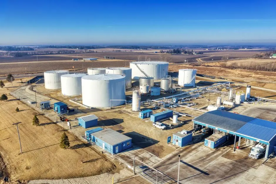
Dissolved air flotation (DAF) pre-treatment must reduce emulsified oil and grease concentration to below 50 mg/L—and ideally below 30 mg/L—to prevent the hydrophobic fouling of downstream moving bed biofilm reactor design carriers (source: HydropureWater process engineering guidelines, 2026). If raw coolant containing 1,000 mg/L of oil enters the MBBR, the oil will coat the carriers, creating an anaerobic barrier that suffocates the heterotrophic biofilm. To achieve this target, the factory must install a highly efficient chemical coagulation and flocculation system upstream of the flotation unit.
For metalworking wastewater pre-treatment, a metalworking DAF pre-treatment unit with a treatment capacity ranging from 4 to 300 m³/h is specified. The process requires dosing an inorganic coagulant, such as polyaluminum chloride (PAC) at 150 to 400 mg/L, to break the oil emulsion, followed by an anionic polyacrylamide flocculant at 2 to 5 mg/L to build heavy, easily floatable flocs. The DAF unit generates micro-bubbles of 10 to 50 µm in diameter, rising at a surface loading rate of 5 to 15 m/h, which lift the encapsulated oil and solids to the surface for mechanical skimming. Following DAF treatment, the wastewater enters an intermediate equalization tank where the pH is adjusted to 6.5–7.5, and nutrients—typically urea and monoammonium phosphate (MAP)—are dosed to achieve a stable BOD:N:P ratio of 100:5:1, correcting the nutrient deficiency typical of industrial coolant streams.
Step 3 — Pick the MBBR Design Loading and HRT
The volumetric BOD loading rate for machining coolant wastewater must be restricted to 0.4 to 1.2 kg BOD/m³·d to account for the inhibitory effects of residual surfactants and biocides (source: industrial wastewater design standards, 2025). This is significantly more conservative than the 1.5 to 3.0 kg BOD/m³·d volumetric BOD loading rates used for highly biodegradable municipal wastewater. Sizing the reactor volume requires a stepwise calculation based on daily mass loading, carrier surface area, and kinetic constraints.
The hydraulic retention time wastewater calculation must be paired with the target effluent quality. For discharge to municipal sewers meeting a COD limit of less than 500 mg/L, a hydraulic retention time of 8 to 12 hours is sufficient. However, if the plant intends to polish the water for reuse, requiring a COD of less than 100 mg/L, the HRT must be extended to 16 to 24 hours. Consider the following worked sizing example:
Worked Sizing Example:
- Design Flow (Q) = 10 m³/h (240 m³/d)
- Post-DAF Influent BOD₅ = 2,500 mg/L (2.5 kg/m³)
- Daily BOD Mass Load = 240 m³/d × 2.5 kg/m³ = 600 kg BOD/d
- Design Volumetric BOD Loading Rate = 0.6 kg BOD/m³·d
- Required Bioreactor Tank Volume = 600 kg BOD/d ÷ 0.6 kg BOD/m³·d = 1,000 m³
- At 1,000 m³ volume and 240 m³/d flow, the resulting HRT is 4.16 days (100 hours), which is necessary for high-strength, undiluted coolant.
- If the stream is pre-diluted or has lower strength (e.g., BOD ≈ 300 mg/L), a 12-hour HRT design yields a tank volume of 120 m³ (10 m³/h × 12 h). At a 40% carrier fill fraction, the biocarrier media bulk volume required is 48 m³.
| Sizing Parameter | Sewer Discharge Design (COD < 500 mg/L) | Water Reuse Design (COD < 100 mg/L) | Engineering Rationale |
|---|---|---|---|
| Volumetric BOD Loading Rate | 0.8 – 1.2 kg BOD/m³·d | 0.4 – 0.6 kg BOD/m³·d | Lower loading rates ensure complete degradation of hard COD fractions |
| Hydraulic Retention Time (HRT) | 8 – 12 hours | 16 – 24 hours | Extended contact time is required for slow-growing nitrifiers and complex organics |
| Target Carrier Fill Fraction | 35% – 45% | 45% – 55% | Higher fill fractions provide the surface area needed for polishing stages |
Step 4 — Specify the Carrier Media and Aeration

Moving bed biofilm reactor carriers manufactured from high-density polyethylene (HDPE) must feature a density range of 0.94 to 0.97 g/cm³ to ensure neutral buoyancy and complete fluidization under standard aeration rates (source: international plastic carrier specifications, 2025). For treating high-viscosity machining coolant wastewater, the selected biocarrier media should possess a high protected specific surface area (between 800 and 1,200 m²/m³) and a large opening or slot size of at least 10 mm. This open structure prevents the thick, viscous biofilm from clogging the internal channels of the carriers, which would otherwise lead to anaerobic dead zones and loss of active surface area.
The aeration system must serve a dual purpose: providing dissolved oxygen (DO) to the heterotrophic biofilm and supplying the mixing energy required to fluidize the carriers. Fine bubble aeration systems utilizing membrane disc diffusers must be installed at a basin floor submergence of 5 to 8 meters. The system must deliver an air supply flux of 0.5 to 0.8 Nm³/min per square meter of basin floor area. This flux maintains the DO concentration above 2.0 mg/L throughout the basin and ensures uniform fluidization of the carriers at bulk fill fractions up to 60%. This intensive mixing strategy aligns with the oxic biological polishing stages evaluated in the 2025 MDPI A2O–MBBR study (doi: 10.20944/preprints202512.0976.v1), which confirmed that robust aeration is critical to achieving low effluent COD concentrations in industrial applications.
| Carrier & Aeration Component | Technical Specification Value | Engineering Standard / Material |
|---|---|---|
| Carrier Material | Virgin High-Density Polyethylene (HDPE) | UV-stabilized, non-recycled polymer |
| Protected Specific Surface Area | > 1,000 m²/m³ | Internal corrugated structure |
| Carrier Bulk Fill Fraction | 30% – 50% of empty tank volume | Optimized for mixing energy constraints |
| Aeration Diffuser Type | Fine-bubble EPDM membrane discs | High oxygen transfer efficiency (SOTE > 6%/m) |
| Target Dissolved Oxygen (DO) | 2.0 – 4.0 mg/L | Continuous optical DO probe feedback control |
Step 5 — Confirm Discharge or Reuse Limits and Sludge Handling
Under the China GB 8978-1996 Class I and II secondary discharge standards, industrial factories discharging treated metalworking wastewater must meet limits of COD less than 500 mg/L, oil and grease less than 10 mg/L, and suspended solids less than 70 mg/L (source: Ministry of Ecology and Environment, China). If the plant's objective is zero liquid discharge (ZLD) or water reuse, the effluent must be polished to a COD of less than 100 mg/L and an oil concentration of less than 1 mg/L. This level of treatment requires routing the MBBR effluent through a secondary separation stage to capture sloughed biofilm solids.
Because MBBR is an attached-growth process, it does not utilize a sludge recycle line. Instead, excess biomass sloughs off the carriers naturally and must be removed downstream. A lamella clarifier for MBBR effluent polishing is recommended to separate these suspended solids from the treated water. The biological sludge production rate for this application ranges from 0.05 to 0.15 kg TSS per kg of BOD removed. The generated chemical and biological sludge from both the DAF and the lamella clarifier must be pumped to a sludge holding tank and dewatered using a plate-and-frame sludge dewatering filter press with a filtration area of 1 to 500 m², yielding a dry, easily disposable sludge cake with a solids content of 30% to 40% by weight.
Frequently Asked Questions
What is the maximum oil concentration an MBBR can tolerate before biofilm failure?
An MBBR can tolerate a maximum of 50 mg/L of free and emulsified oil, though operating below 30 mg/L is highly recommended to prevent hydrophobic coating of the biocarrier media (source: HydropureWater field data, 2026).
How does the cost of an MBBR compare to an MBR for machining coolant treatment?
For a complete economic evaluation of capital and operating costs between these two biological systems, refer to our detailed MBR vs MBBR 2026 cost breakdown.
Can MBBR achieve complete reuse standards for CNC coolant blowdown?
Yes, but it requires a multi-barrier approach where the MBBR acts as the core biological stage, followed by advanced filtration; see our MBBR configuration guide for machining coolant blowdown for discharge and reuse optimization.