Why Paint Booth Curtain Water Breaks Generic ZLD Designs
Untreated water-wash paint booth discharge contains up to 10% uncured polymeric resins, solvent-bearing solids, and volatile organic compounds (VOCs) that cause rapid irreversible membrane fouling within 48 to 72 operating hours (source: HydropureWater field data, 2026). Unlike cooling-tower blowdown or reverse osmosis (RO) reject—the benign inorganic feed streams that conventional zero liquid discharge systems are designed to process—paint booth curtain water carries a complex, multi-phase organic load. This includes sticky overspray paint particles, solvent slugs from two-component (2K) clear-coat dump-and-fill operations, isocyanate residues, and floating fibers or rags.
According to a comprehensive evaluation of zero liquid discharge technology published in the Journal of Water Process Engineering (per ScienceDirect, 2022), ZLD is classified as a highly critical review technology. However, the academic literature and standard vendor offerings predominantly focus on thermal power, textile dyeing, and seawater desalination. Industrial paint line ZLD remains a documented engineering gap. Generic systems fail because they do not account for the unique fouling chemistry of water-borne and solvent-borne paint binders.
When generic ZLD designs are applied to this wastewater, they fail via two distinct mechanisms: organic compaction of the RO membranes and severe foaming or scaling in the thermal evaporation stage. Polyamide RO membranes are rapidly blinded by emulsified solvents and polymers, while the thermal evaporators experience massive foaming episodes that carry volatile organics into the distillate, ruining the water quality. Achieving a successful closed-loop design requires an engineering approach tailored specifically to the physical-chemical properties of paint overspray wastewater.
Step 1 — Characterize the Curtain Water Before You Size Anything
Industrial paint booth curtain water exhibits chemical oxygen demand (COD) fluctuations ranging from 500 mg/L to over 6,000 mg/L depending on the production cycle (source: HydropureWater field data, 2026). To establish a defensible design basis, process engineers must collect samples across at least three distinct operating states: shift start, mid-shift, and immediately following a clear-coat changeover. Volatile organic compound (VOC) and total dissolved solids (TDS) swings of 300% to 500% are common during these transitions and must be accounted for in the mass balance.
The standard analytical testing panel for paint booth scrubber zero discharge must capture both soluble and insoluble fractions. Key parameters include flow rate (m³/hr), pH, operating temperature, total suspended solids (TSS), TDS, COD, oil & grease (O&G), total Kjeldahl nitrogen (TKN), and specific paint solvents (such as xylene, toluene, methyl ethyl ketone, and isocyanates) analyzed via GC-MS. 2026 plant surveys must test for PFAS in the surfactant packages of water-borne coatings, as environmental regulators are rapidly tightening discharge limits on these persistent compounds (PFAS paint booth discharge 2026).
The table below outlines the typical raw wastewater design envelope for medium-to-heavy industrial paint lines, alongside the essential operational metrics required to size the downstream treatment equipment:
| Parameter / Operational Metric | Typical Range (Low to High-Duty) | Sizing Relevance |
|---|---|---|
| Total Dissolved Solids (TDS) | 1,000 – 8,000 mg/L | Determines maximum RO recovery and MEE boiling point rise |
| Chemical Oxygen Demand (COD) | 500 – 6,000 mg/L | Dictates DAF chemical dosing and carbon polishing requirements |
| Total Suspended Solids (TSS) | 200 – 2,000 mg/L | Sizes the coagulation, DAF, and lamella clarifier stages |
| Oil & Grease (O&G) | 50 – 500 mg/L | Determines DAF surface loading and microbubble air-to-solids ratio |
| Daily Paint Consumption | 500 – 3,000 L/day | Defines the daily mass of overspray solids entering the water loop |
| Operating Hours | 80 – 120 hours/week | Establishes equalization tank buffer volumes |
Step 2 — Pretreatment Train: Coagulation, DAF, Lamella, Media, UF
Pretreatment trains for paint overspray wastewater must achieve a silt density index (SDI) of less than 3.0 to protect downstream spiral-wound polyamide membranes from irreversible organic compaction (source: HydropureWater engineering guidelines, 2026). A generic filtration loop cannot achieve this level of purification. Instead, a multi-stage physical-chemical pretreatment train is required to systematically remove sticky solids, emulsified solvents, and colloidal binders before the water reaches the membrane stage.
The engineered pretreatment sequence consists of four primary unit operations:
- Step 2a: Coagulation and Flotation. An automatic chemical dosing skid introduces polyaluminum chloride (PAC) (50–200 mg/L) and an anionic polymer to de-tackify and flocculate the paint binders. A paint-compatible DAF unit then separates the flocculated paint solids, removing 85% to 95% of the raw TSS and free oils. For systems handling highly concentrated solvent streams, process details can be cross-referenced with our engineering guide on DAF configuration for solvent stripper dilute.
- Step 2b: Gravity Clarification. A lamella clarifier for paint solids polishing processes the DAF effluent. Operating at a conservative surface loading rate of 20 to 40 m³/m²·h, it drops the remaining bulk TSS below 50 mg/L and acts as a gravity thickener for the settled sludge.
- Step 2c: Media Filtration. A pressurized multi-media filter for SDI reduction containing graded sand, anthracite, and garnet captures fine suspended particles, bringing the turbidity down to less than 1 NTU.
- Step 2d: Ultrafiltration Guard. A hollow-fiber ultrafiltration (UF) system (0.01–0.05 μm PVDF) serves as the final barrier. The UF permeate consistently exhibits an SDI of less than 2.0, satisfying the strict warranty conditions of high-pressure RO membranes.
For paint lines running solvent-heavy formulations, a granular activated carbon (GAC) bed is installed between the multi-media filter and the UF system to adsorb dissolved VOCs, preventing solvent-induced swelling of the UF and RO membrane polymers.
| Pretreatment Unit | Primary Sizing Parameter | Typical Operating Value | Target Effluent Quality |
|---|---|---|---|
| Chemical Dosing / Coagulation | Reaction residence time | 15 – 20 minutes | De-tackified, stable flocs |
| Dissolved Air Flotation (DAF) | Hydraulic loading rate | 4 – 6 m³/m²·h | TSS < 100 mg/L, O&G < 20 mg/L |
| Lamella Clarifier | Projected plate settling area | 0.5 – 0.8 m² per m³/hr of feed | TSS < 30 mg/L |
| Ultrafiltration (UF) Guard | Membrane operating flux | 45 – 60 L/m²·hr | SDI < 2.0, Turbidity < 0.1 NTU |
Step 3 — Size the RO for the Permeate/Reject Split
Polymer-modified wastewater treatment configurations limit maximum reverse osmosis recovery rates to a ceiling of 75% to 85% to prevent the precipitation of sparingly soluble silica and organic complexes on the membrane surface (per Panagopoulos & Michailidis, 2025). Attempting to operate above an 85% recovery rate on paint-line wastewater triggers severe scaling, even with high-performance antiscalant dosing. The design must balance high clean-water recovery with long-term membrane run-times.
To avoid rapid fouling, a high-recovery industrial RO system treating pretreated paint booth water must be designed with a conservative membrane flux of 15 to 20 L/m²·hr. Higher flux rates (above 25 L/m²·hr) lead to concentration polarization at the membrane surface, accelerating the deposition of residual organic binders. Sizing the system requires calculating the membrane surface area based on the desired permeate flow and the design flux.
For example, to process a 10 m³/hr feed stream at an 80% recovery rate, the sizing calculations are structured as follows:
- Permeate Flow Rate: 10 m³/hr × 0.80 = 8.0 m³/hr (recycled directly to the booth scrubber circulation loop).
- Required Membrane Area: At a design flux of 18 L/m²·hr, the required active membrane area is:
Area = (10,000 L/hr) / (18 L/m²·hr) = 555 m²
Using standard 8040 brackish-water elements (each providing 40 m² of active area), this configuration requires 14 membrane elements arranged in a 2:1 or 2:2:1 array to maintain optimal cross-flow velocities. - Energy Consumption: The high-pressure RO stage consumes 0.7 to 1.2 kWh per m³ of permeate produced, with the total multi-stage RO skid drawing 1.5 to 2.5 kWh per m³ of raw feed water.
Step 4 — Concentrate and Crystallize: MEE, MVC, and the Final Brine
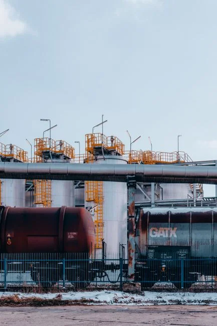
Thermal concentration of industrial reverse osmosis brine requires an energy input of 25 to 65 kWh per cubic meter of feed water processed depending on whether mechanical vapor compression or multi-effect evaporation is selected (per ScienceDirect, 2022). Because thermal evaporation is highly energy-intensive, the preceding RO stage must be optimized to minimize the volume of brine sent to the evaporators. Sizing the thermal system depends on the daily volume of RO reject and the specific boiling point rise of the concentrated salts.
For paint lines with an RO reject flow below 5 m³/hr, Mechanical Vapor Compression (MVC) is the industry-standard choice in 2026. MVC systems operate under vacuum at low temperatures (typically 55 °C to 60 °C), which prevents the baking and scaling of residual paint resins on the heat exchanger tubes. For larger facilities with reject flows exceeding 5 m³/hr, a steam-driven Multi-Effect Evaporator (MEE) is preferred to take advantage of available plant steam and reduce electrical demand.
The crystallizer stage receives the concentrated brine (at approximately 150,000 to 180,000 mg/L TDS) and drives it past the saturation limit to over 250,000 mg/L TDS, forcing salt crystallization. The resulting slurry is routed to a heavy-duty plate-and-frame filter press for paint sludge dewatering. This dewatering step yields a dry salt cake (typically mixed sodium/calcium sulfate-chloride salts) with a solid content of 75% to 80%, suitable for landfill disposal or potential industrial salt reclamation.
To compare these thermal configurations with other industrial sectors—such as textile mercerizing or cleanroom CIP loops—refer to our technical guides on ZLD configuration for mercerizing rinse and MBR configuration for cleanroom CIP wastewater.
| Thermal Technology | Typical Feed Flow Range | Specific Energy Consumption | Fouling Risk & Mitigation |
|---|---|---|---|
| Mechanical Vapor Compression (MVC) | 1 – 5 m³/hr | 25 – 45 kWh/m³ | Low (under 60 °C operation prevents organic baking) |
| Multi-Effect Evaporator (MEE) | > 5 m³/hr | 35 – 65 kWh/m³ (steam equivalent) | Medium (requires chemical descaling cycles) |
| Forced-Circulation Crystallizer | 0.2 – 1.5 m³/hr | 50 – 80 kWh/m³ | High (requires high-shear velocities to prevent tube plugging) |
Capex, Opex, and the 2026 Compliance Trigger
Capital expenditure for an industrial paint-line zero liquid discharge (ZLD) facility processing 5 to 10 cubic meters per hour ranges from USD 1.8 million to USD 3.5 million in 2026 (source: HydropureWater market analysis, 2026). The high capital cost is driven by the thermal concentration and crystallization stages, which represent 60% to 70% of the total equipment package. The remaining capital is allocated to the chemical pretreatment skids, lamella clarifiers, and membrane filtration systems.
Operating costs (Opex) range from USD 2.50 to USD 6.00 per m³ of treated curtain water. This cost is driven by three main factors: electrical energy for the MVC/RO pumps, chemical consumables (PAC, polymers, and antiscalants), and the disposal costs of the dewatered crystallizer cake. Despite these costs, the investment is increasingly justified by regulatory and financial drivers in 2026:
- PFAS and VOC Discharge Limits: Environmental protection agencies have implemented strict discharge limits on VOCs and PFAS surfactant compounds, making untreated sewer discharge legally impossible for many automotive and aerospace finishers.
- Water Scarcity Tariffs: Industrial freshwater tariffs have risen significantly, improving the return on investment (ROI) of recycling 80% of the curtain water back to the paint booth.
- Corporate ESG Mandates: Major automotive OEMs and Tier-1 suppliers have established "Net-Zero Water" goals for 2026, requiring plants to eliminate liquid discharges to maintain supplier status.
A simple payback heuristic applies: when combined municipal sewer discharge fees and freshwater supply costs exceed USD 3.50/m³, an industrial paint line ZLD system achieves ROI parity over a 7 to 10-year operational horizon.
Frequently Asked Questions
Regulatory frameworks in 2026 classify water-wash paint booth discharge as a high-strength industrial stream requiring advanced multi-stage treatment prior to reuse or discharge (per EPA guidelines).
How do you size ZLD for a factory discharging paint booth curtain water?
To size the ZLD system, you must design a mass balance based on peak TDS (1,000–8,000 mg/L) and TSS (200–2,000 mg/L) rather than average volumetric flow. The DAF and lamella systems are sized for 100% of the forward flow, the RO system is sized for a maximum 80% recovery limit, and the thermal evaporator is sized to concentrate the remaining 20% reject stream (source: HydropureWater engineering guidelines, 2026).
Is a DAF system alone sufficient for paint booth scrubber zero discharge?
No, a DAF system only removes suspended solids and free oils. While it achieves 85% to 95% TSS removal, it cannot remove dissolved solids (TDS) or highly soluble solvents, which will accumulate in the recirculating water and eventually ruin paint finishes (source: HydropureWater field data, 2026).
What is a realistic RO recovery rate for paint overspray wastewater?
A realistic recovery rate is 75% to 85% (per Panagopoulos & Michailidis, 2025). Attempting to push recovery beyond 85% causes rapid organic scaling and silica precipitation on the membrane surfaces, dramatically increasing cleaning frequency and reducing element lifespan.
How do you handle solvent spikes in an industrial paint line ZLD system?
Solvent spikes are managed by placing a granular activated carbon (GAC) filter or an organoclay bed directly upstream of the ultrafiltration (UF) guard membrane. This setup strips volatile organic compounds (VOCs) and prevents solvent-induced swelling of the polymeric membranes (source: HydropureWater design standards, 2026).