Start with four decisions that define the Jammu treatment scope
A Jammu data center should define treatment from its actual cooling architecture and measured wastewater streams, not from a generic ETP concept. Confirm whether cooling is evaporative, sealed liquid, or hybrid; segregate sewage, washdown, floor drainage, leakage, maintenance flow, cooling blowdown, and RO concentrate; establish representative chemistry; and secure written acceptance for every reuse, discharge, and residue route. Equipment selection remains provisional until these four procurement gates close.
IDE’s 2026 report states that conventional evaporative cooling can lose up to 85% of its water to the atmosphere, while sealed non-evaporative loops virtually eliminate evaporation loss. This changes both the wastewater volume and composition: an evaporative or hybrid facility is likely to have a continuous blowdown duty, while a sealed loop may be dominated by leakage and maintenance drainage. Use the cooling-blowdown reuse engineering guide as a reference framework, not as a substitute for Jammu measurements.
| Procurement gate | Minimum evidence required | Decision consequence |
|---|---|---|
| Cooling architecture | Evaporative, sealed, or hybrid arrangement; operating modes; future IT-load assumptions | Defines whether blowdown is a major continuous stream or a minor intermittent stream |
| Measured water balance | Metered make-up, evaporation, blowdown, leakage, drainage, permeate, concentrate, and reuse demand | Sets preliminary flow boundaries and identifies missing meters |
| Representative chemistry | Samples across operating modes and representative loads | Determines treatment objectives and scaling risk |
| Accepted endpoints | Written reuse or discharge criteria and an accepted concentrate, sludge, or precipitate destination | Converts a treatment concept into a procurable project |
The final gate is easy to underestimate. A technically effective treatment train has little commercial value if its permeate has no approved use or its concentrate has no authorized destination. The regional data center treatment decision framework reinforces the need to close those items before finalizing the package.
Build a metered water balance for every wastewater stream
Equipment sizing should follow metered peak flows and the complete water balance, not average daily facility consumption. Meter make-up, evaporation, blowdown, leakage, maintenance drainage, permeate, concentrate, reclaimed-water demand, and final discharge as one linked system. Short-duration startup dumps, maintenance events, and emergency-dump routes can govern equipment capacity even when they contribute little to the daily average.
- Measure cooling make-up, evaporation, and blowdown at the operating modes proposed for the Jammu facility.
- Measure closed-loop leakage, maintenance drainage, washdown, floor drainage, and sewage separately.
- Record permeate and concentrate flow from any treatment or desalination system already on site.
- Reconcile reclaimed-water demand and final discharge with the measured inflow and evaporation boundaries.
- Size equalization and treatment equipment for measured peaks, emergency conditions, and future operating modes.
HydropureWater’s 2026 guidance provides a preliminary relationship: blowdown equals 1 divided by CoC minus 1. That produces 25% of make-up at 4 CoC and 20% at 6 CoC. The same guidance warns that actual blowdown may exceed theoretical values by 15–30% because of unmeasured losses and emergency dumps. These percentages are screening relationships, not Jammu design factors; site meters and operating records must replace them before award.
| Water-balance input | Measurement required | Use in design |
|---|---|---|
| Cooling make-up and evaporation | Continuous or campaign metering linked to IT load and operating mode | Reconciles blowdown and identifies the dominant water demand |
| Cooling blowdown | Measured peak flow and chemistry across representative loads | Sets UF, RO, equalization, and concentrate-handling duty |
| Leakage and maintenance drainage | Event-based flow, duration, and coolant or additive inventory | Determines segregation, storage, specialist recovery, or disposal needs |
| Sewage, washdown, and floor drainage | Flow-duration profile and representative pollutant analysis | Defines biological, solids-removal, disinfection, or polishing scope |
| Permeate, concentrate, and final discharge | Independent flow metering and destination records | Closes the balance and exposes rejected water volumes |
Do not import IDE’s 2026 illustration of up to 2 million litres per day for a 100-MW facility into the Jammu calculation. IDE presents that figure as an illustration, not as local operating data. The stream-by-stream water-balance method is useful only when every term is replaced with site evidence.
Match each stream to its treatment objective
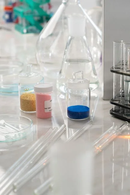
Sanitary sewage, contaminated drainage, and cooling blowdown have different contaminants and endpoints, so combining them before characterization can make both treatment and compliance less defensible. Characterize each stream separately, establish its intended destination, and then decide whether equalization or polishing can justify a shared downstream step.
Sanitary sewage
Obtain BOD, COD, TSS, nutrients, microbiology, and flow-duration data. Compare biological treatment and solids separation with disinfection or reuse polishing. An MBR membrane bioreactor for biological treatment and solids separation may suit a sewage or reuse train, but its published catalog range of 10–2,000 m³/day is a selection envelope, not evidence of Jammu capacity or effluent performance.
Washdown and oily floor drainage
Start with screening, equalization, and oil-and-grease removal. Determine whether biological treatment or further polishing is needed from measured pollutant data rather than assuming that dilution makes the stream suitable for the sewage plant or cooling system.
Closed-loop leakage and maintenance drainage
Document the coolant identity and additives, and assess whether refrigerant- or PFAS-containing fluids could be present. Until compatibility is established, specialist recovery or controlled disposal may be necessary. Leakage should not be assumed suitable for cooling make-up merely because it originates inside the facility.
Evaporative cooling blowdown
Sample across cooling modes and representative IT loads for flow, conductivity or TDS, pH, hardness, silica, TSS, chlorides, sulfate, alkalinity, temperature, and chemical residuals. This dataset defines the scaling, corrosion, fouling, and microbiological risks that the treatment train must control.
| Stream | Primary characterization | Potential treatment objective | Critical unresolved item |
|---|---|---|---|
| Sanitary sewage | BOD, COD, TSS, nutrients, microbiology, flow duration | Biological treatment, solids separation, disinfection or reuse polishing | Reuse specification and measured flow range |
| Washdown and floor drainage | Screening needs, equalization demand, oil and grease, event flow | Screening, equalization, oil-and-grease removal, then assessed polishing | Release point and accepted discharge route |
| Leakage and maintenance flow | Coolant identity, additives, contamination risk | Specialist recovery or controlled disposal | Whether restricted substances are present |
| Cooling blowdown | Scaling ions, TDS, TSS, microbiology, temperature, residual chemicals | Particulate control, dissolved-salt removal where required, and cooling-chemical protection | Feed-specific recovery and concentrate capacity |
Where particulates must be controlled before RO, evaluate UF pretreatment for cooling blowdown reuse. Its published 0.03-micron PVDF membrane, 2,000–40,000 L/h capacity, feed turbidity up to 300 ppm, automatic backwash, and air scour are catalog selection parameters. They are not guarantees for Jammu feed chemistry, peak flow, recovery, or life-cycle performance.
Design cooling-blowdown reuse around scaling and recovery
Conventional UF/RO reuse is credible only when the feed-specific scaling calculation, permeate specification, and concentrate route support the required cooling recovery. Suspended solids, colloids, and particles should be removed first because they can foul membranes, instruments, and cooling-distribution systems. Dissolved-salt removal follows where the cooling make-up specification requires it.
Project RO recovery from feed TDS, calcium hardness, silica, temperature, antiscalant strategy, and site-specific scaling limits. IDE’s 2026 report states that conventional brackish-water RO commonly reaches 75–80% recovery before scaling becomes unmanageable. Treat that as a screening benchmark only. An industrial RO system for cooling make-up recovery should be evaluated on representative-feed performance, not its catalog maximum of up to 95% recovery.
A specialist high-recovery train may be justified when conventional RO cannot meet the site recovery target reliably. IDE’s 2026 industrial example achieved approximately 95% recovery and about 1 mg/L permeate silica on a blended stream comprising blowdown from 20 hybrid cooling towers, RO brine, and manufacturing wastewater. That installation also required controlled precipitation and a route for the resulting solid residue. It is proof-of-concept evidence for that specific mixed industrial feed, not a transferable guarantee for a Jammu data center.
| Design issue | Conventional UF/RO approach | Specialist high-recovery approach | Acceptance evidence |
|---|---|---|---|
| Particulate control | UF before RO | Specialist solids handling as required | Turbidity, TSS, differential-pressure trend, and cleaning record |
| Salt removal | RO within site-specific scaling limits | Combined membrane and precipitation or crystallization approach | Feed-specific recovery and permeate chemistry |
| Concentrate and solids | Accepted concentrate route required | Controlled precipitation and solid-residue route required | Written destination and handling acceptance |
| Cooling make-up | TDS, TSS, scaling, microbiology, residual chemistry, and materials compatibility | Same specification plus validated control strategy | Pilot reuse and material-compatibility evidence |
Define the cooling make-up specification before selecting high recovery. It should cover TDS, suspended solids, scaling tendency, microbiology, residual chemistry, and materials compatibility with the cooling distribution system. Membrane elements and related hardware can be aligned later through the RO and UF membrane-element guide, but catalog ratings do not establish site performance.
Compare discharge, internal reuse and high-recovery alternatives
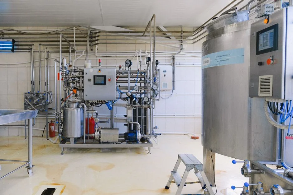
Discharge, non-contact reuse, cooling make-up reuse, and specialist high-recovery treatment should be compared against the receiving route’s chemistry, temperature, solids, microbiology, and residue requirements. The selected endpoint determines whether the project is fundamentally an effluent-compliance project, a water-supply project, or both.
Open Engineering’s 2026 preprint found that its wastewater scenario had about twice the global warming potential of the freshwater case, with treatment energy accounting for roughly 80% of the difference. Its UF+RO scenario used more than five times the freshwater case’s energy, partly offset by improved cycles of concentration that reduced blowdown and chemical consumption. These findings frame the operational trade-off; they are not Indian legal limits.
| Endpoint | When it is credible | Key acceptance condition | Main risk to price |
|---|---|---|---|
| Controlled discharge | The receiving authority accepts the treated stream’s chemistry, temperature, solids, and additives | Written discharge criteria | Disposal route, pretreatment, and compliance controls |
| Washdown or non-contact reuse | Recovered water meets the specified application and storage or distribution controls | Defined reuse specification | Additional storage, distribution, and quality monitoring |
| Cooling make-up reuse | TDS, suspended solids, scaling, microbiology, residual chemistry, and compatibility protect the cooling system | Feed-specific pilot proof and cooling-operability criteria | UF/RO equipment, cleaning, chemical use, and concentrate handling |
| Specialist high recovery | Conventional treatment cannot meet the required recovery reliably | Stable representative-feed recovery plus an approved residue route | Specialist equipment, solids handling, controls, and operator capability |
Require separate written acceptance for treated effluent and for RO concentrate, sludge, or precipitated solids. Approval of one stream does not automatically cover another. The data center wastewater treatment comparison is useful for structuring the commercial choice, but the selected Jammu authority or sewer operator must provide the governing criteria.
Turn the concept into a Jammu tender and acceptance plan
The tender should convert the four closed procurement gates into measurable bidder submissions. Issue a request for information covering cooling architecture; measured make-up, blowdown, leakage, and maintenance flows; cycles of concentration; representative analyses; coolant inventory; reuse or discharge criteria; and the concentrate destination. Include peak conditions, emergency-dump routes, operating modes, future IT-load assumptions, and downstream material-compatibility requirements.
HydropureWater’s 2026 guidance proposes a trial lasting 3–6 months, or the longest practical operating window, to cover representative cooling demand, startup conditions, treatment operation, and concentrate handling. During the trial, monitor flow, conductivity, pH, hardness, silica, TSS, the selected biocide residual, and differential pressure across membrane or filter stages. Trend cycles of concentration, actual recovery, cleaning frequency, chemical consumption, and reuse performance.
| Tender package | Minimum bidder submission | Acceptance basis |
|---|---|---|
| Design basis | Water balance, operating modes, peak and emergency conditions, representative chemistry, and endpoint criteria | Bidder assumptions traceable to measured site data |
| Pilot evidence | Feed-specific recovery, permeate quality, cleaning frequency, chemical use, and concentrate handling | Stable performance over the agreed operating window |
| Commercial schedule | Equipment, installation, membranes, chemicals, energy, testing, operator time, cleaning, redundancy, replacement parts, and residue handling | Itemized total cost for comparable scopes |
| Performance contract | Guaranteed flow, recovered-water quality, recovery, cleaning limits, controls, and residue route | Representative Jammu feed operation, not a catalog maximum |
Contract only the stable recovery demonstrated with representative Jammu feed chemistry and pilot operation, including cleaning, chemical-use, and concentrate-handling conditions. Require the supplier to identify every projection assumption and explain how site data supports it. Use the tender and acceptance sequence for a new data center and the data center wastewater treatment planning guide as drafting references, while retaining only requirements verified for Jammu.
Frequently Asked Questions
What is the cheapest defensible treatment option for a Jammu data center?
The supplied research contains no Jammu tariff, measured flow, site chemistry, or equipment quotation, so it does not support a defensible price or a claim that one technology is cheapest. Require itemized site-specific bids covering equipment, installation, membranes, chemicals, energy, testing, operator time, cleaning, redundancy, replacement parts, and residue handling. Compare those bids only after bidders use the same measured water balance, reuse target, discharge route, and concentrate scope.
Should a Jammu data center guarantee 95% RO recovery?
No supplier should guarantee 95% recovery from a catalog rating alone. IDE’s 2026 industrial example achieved approximately 95% recovery on a mixed industrial stream, while the same report states that conventional brackish-water RO commonly reaches 75–80%. Contract only stable recovery demonstrated with representative Jammu feed chemistry and pilot operation, including cleaning, chemical use, and concentrate handling.
What cooling blowdown flow should be used for equipment sizing?
Use measured peak flow and the complete data center water balance, including startup dumps, maintenance events, and emergency-dump routes. The 2026 CoC relationships—25% of make-up at 4 CoC and 20% at 6 CoC—are preliminary checks, not Jammu sizing inputs. The measured balance must also reconcile evaporation, leakage, permeate, concentrate, reuse, and final discharge.
Can sewage and cooling-tower blowdown be treated in one plant?
Do not combine them without water-quality, reuse, and compliance evidence. Sewage requires biological and solids-removal objectives, while cooling blowdown requires scaling, corrosion, microbiology, and residual-chemistry controls. A common downstream polishing or disposal step may be feasible, but the mixed influent must be characterized and accepted for the specified endpoint.
Which approval should be obtained before ordering treatment equipment?
Obtain written acceptance criteria covering both the treated effluent and the concentrate, sludge, or precipitated solids from the relevant Jammu authority or sewer operator. Confirm the selected reuse or discharge route, required parameters, monitoring conditions, and residue destination before finalizing equipment specifications and pilot acceptance tests.