What Johor Bahru Data Centers Must Solve
A Johor Bahru data center needs a treatment strategy that protects cooling reliability while reducing dependence on municipal water. In August 2025, Johor’s data center tariff reached RM5.33 per cubic metre, while a 100MW facility was reported to use about 4.16 million litres of cooling water daily. The practical options are treatment of reclaimed effluent for cooling make-up, recovery of cooling tower blowdown, or both. Feasibility depends on source chemistry, silica and hardness, biological risk, cooling cycles of concentration, space, residual disposal and the required discharge route. Equipment selection should therefore be based on a site water balance and verified analysis—not water-use estimates alone.
The issue extends beyond environmental permitting because every interruption in make-up water can constrain cooling capacity. The Straits Times reported in August 2025 that Johor had 47 planned and operational data centres, 5.7GW of planned capacity and 487MW already live, citing a July 2025 DC Byte report. The same report stated that the data centre tariff rose to RM5.33 per cubic metre from August 2025, RM1 to RM1.75 above the previous general non-domestic tariff. Higher withdrawal costs strengthen the commercial case for reuse, but a tariff saving is valuable only if the recovered stream does not introduce fouling, corrosion, biological or discharge risks.
Water stewardship is also becoming an approval issue. In November 2024, a Johor official said almost 30% of data centre applications had been rejected because of concerns over unsustainable water and power practices. A credible project therefore needs an auditable source strategy, treatment rationale, residual plan and water balance—not a general statement supporting sustainability.
For scale, The Straits Times reported in August 2025 that a 100MW data centre uses about 1.1 million gallons, or 4.16 million litres, of water daily for cooling. That is a reference point, not a design flow. Further planning should account for cooling configuration, utilisation, evaporation and operating conditions. The wider data center development and wastewater planning context also shows why water treatment belongs in early site and utility decisions.
Choose the Right Water Source for Cooling
External reclaimed water and internal cooling tower blowdown recovery solve different problems and should be evaluated separately. The first requires a dependable wastewater supply and a robust treatment train; the second reduces the facility’s own discharge and withdrawals but is constrained by concentration and scaling chemistry inside the cooling loop.
| Source | Supply role | Principal treatment issue | Key project questions |
|---|---|---|---|
| Municipal treated water | Baseline cooling make-up | Water cost, availability and source quality | Can the utility meet peak and abnormal demand? |
| Externally supplied reclaimed water | Alternative cooling make-up | Variable solids, organics, salts, biological load and supply continuity | Is there an enforceable supply agreement and suitable pretreatment? |
| On-site treatment of treated effluent | Converts external effluent into controlled make-up | Full wastewater-to-cooling treatment train and residual handling | What feed variability can the plant accept, and where will concentrates go? |
| Cooling tower blowdown recovery | Internal reclaimed-water source | Silica, hardness, scaling, membrane fouling and chemical accumulation | Can recovery be sustained without transferring risk to the cooling system? |
Bridge provides a relevant Johor precedent. Data Center Dynamics reported on 6 August 2025 that Bridge described itself as the first Johor data centre to repurpose treated effluent as reclaimed water for operational use. It had signed an MoU with Johor Special Water and was working with IWK, JSW and Permodalan Darul Ta’zim.
The Straits Times reported in August 2025 that Bridge’s reclamation plant receives sewage effluent from an IWK plant approximately 6.5km away. It also reported that IWK had agreed to supply 12 million litres per day to Bridge and Computility. This demonstrates access to a treated-effluent source, but it does not remove the need to verify chemistry, contract terms, interruption tolerance and discharge responsibility.
Request source-specific analyses covering turbidity, suspended solids, hardness, silica, conductivity, chloride, sulfate, biological indicators, temperature and seasonal variation. Nominal effluent quality cannot define membrane life, cooling compatibility or storage conditions. The broader data center wastewater and cooling blowdown treatment framework explains why source selection and treatment design must be treated as linked decisions.
Build a Wastewater-to-Cooling-Water Treatment Train

A reliable treatment train separates contamination control from salt control and gives operators a controlled point of entry into the cooling system. The required sequence depends on feed quality, but it should normally address reception and flow control, solids removal, filtration, biological risk where relevant, membrane pretreatment, salt control where required, disinfection, storage and controlled make-up.
| Stage | Engineering purpose | Design information to verify |
|---|---|---|
| Reception and flow control | Match incoming flow to treatment and storage capacity | Supply profile, interruption conditions and equalisation requirements |
| Screening and solids removal | Protect pumps, filters and downstream equipment | Debris load, particle characteristics and sludge destination |
| Filtration or ultrafiltration | Remove suspended solids, colloids and biological material before RO | Feed limits, backwash method, membrane materials and differential-pressure control |
| Biological treatment where necessary | Reduce degradable organics and associated oxygen demand | Whether the upstream effluent requires further biological treatment |
| RO where salt control is required | Reduce dissolved salts that affect scaling and cooling chemistry | Recovery target, concentrate composition, pretreatment and cleaning strategy |
| Disinfection and storage | Limit biological growth before entering the cooling system | Residual target, contact control, tank hygiene and residence time |
| Controlled cooling make-up | Prevent untreated or off-spec water entering the loop | Interlocks, diversion, level control and chemistry limits |
Bridge’s Johor plant provides a local reference. The Straits Times reported in August 2025 that sewage effluent was pumped into tanks at the Ulu Tiram facility for odour and impurity removal before passing through three passes of reverse-osmosis membranes contained in dozens of cylinders. The reported arrangement confirms the importance of upstream treatment before RO, but it does not establish the final configuration required for another site.
For clarified or recycled wastewater, ultrafiltration pretreatment for reclaimed wastewater can protect downstream membranes by removing bacteria, colloids and suspended solids. The referenced HydropureWater system specification identifies 0.03-micron PVDF membranes, turbidity acceptance up to 300 ppm, automatic backwash and air scour; these are equipment-specific claims, not guaranteed performance for every Johor feed.
Final selection must follow the water balance, source analysis and pilot work. Source chemistry, required make-up quality, flow variability and recovery determine whether UF alone, UF followed by RO or another validated configuration is appropriate. An industrial RO system for cooling make-up water should therefore be specified against measured feed limits and cooling chemistry—not selected by nominal capacity alone.
Treat Cooling Tower Blowdown for Internal Reuse
Cooling tower blowdown recovery can reduce freshwater withdrawal, but evaporation concentrates the substances most likely to foul membranes or scale the cooling system. The decision should begin with chemistry rather than a recovery percentage.
In an evaporative cooling loop, evaporation leaves dissolved salts behind. Periodic blowdown then removes water containing mineral deposits, treatment chemicals and microbiological by-products. Increasing the cooling tower cycles of concentration can reduce blowdown, but it also increases the scaling risk unless the incoming make-up water and chemical programme are designed for it.
IDE’s 2026 technical explanation states that conventional brackish-water reverse osmosis is commonly limited to about 75–80% recovery before scaling becomes unmanageable. It describes an alternative architecture that applies conservative local RO, precipitates silica and calcium salts in a fluidized-bed reactor, and recovers the remaining sodium-chloride-dominant brine within a closed loop.
| Evaluation item | Conventional brackish-water RO | High-recovery or salt-recovery design |
|---|---|---|
| Primary advantage | Established separation with comparatively conventional equipment | Potential to recover more water by separating scale-forming salts from residual brine |
| Main limitation | Recovery commonly limited to about 75–80% by scaling, according to IDE’s 2026 explanation | Additional process stages, solids handling and more complex controls |
| Required feed evidence | Silica, calcium, hardness, alkalinity, sulfate, conductivity, chloride and TDS | Same core chemistry plus detailed precipitation and residual-management assessment |
| Residual risk | Concentrate requiring an identified disposal route | Precipitated solids and residual brine requiring explicit destinations and regulatory basis |
| Evidence status | Comparative recovery range, not a guaranteed project specification | IDE reports an industrial desalter at around 95% recovery with permeate silica of about 1 mg/L; this is not guaranteed for a data centre |
The industrial desalter example in IDE’s article mixed cooling-tower, RO and manufacturing wastewaters, so it cannot be transferred directly to a Johor data centre. Before comparing conventional RO with a high-recovery design, test silica, calcium, hardness, alkalinity, sulfate, conductivity, chloride, total dissolved solids and treatment chemicals. Also establish where rejected brine, precipitate and sludge will go.
The cooling blowdown recovery and treatment guide provides a useful process framework, but the final architecture must reflect local discharge routes, residual acceptance and the selected cooling chemistry.
Match Treatment Capacity to the Cooling Water Balance
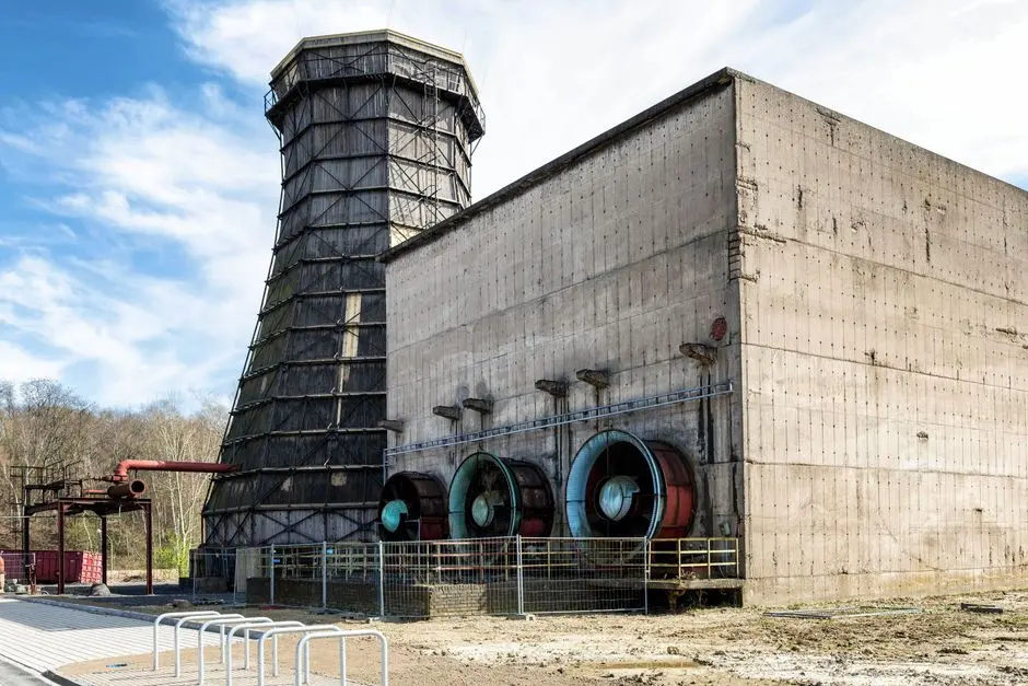
Treatment capacity must be derived from a measured cooling-loop water balance, not multiplied from a headline facility-consumption figure. The sizing sequence is:
- Measure gross make-up demand and separate evaporation, drift and blowdown.
- Establish the operating cooling tower cycles of concentration and the resulting concentration limits.
- Calculate net freshwater withdrawal after external reclaimed water and recovered blowdown are credited.
- Size treatment units for required operating redundancy rather than nominal peak demand alone.
Bridge’s plant provides a local scale benchmark. The Straits Times reported in August 2025 that it processed 5 million litres daily, with expansion to 20 million litres depending on data centre demand. That progression illustrates why modular treatment can align staged campus development with uncertain demand.
The reported 4.16-million-litre daily cooling use for a 100MW facility must not be treated as a guaranteed design flow. Cooling technology, climate, utilisation and cycles of concentration determine actual demand. A project should therefore reconcile the water balance with equipment curves rather than size the plant directly from IT capacity.
Include peak-hour and abnormal-event cases: simultaneous fill, membrane cleaning, treated-water storage, power loss, high feed turbidity and loss of the upstream reclaimed-water connection. The governing question is how much cooling operation can continue while treatment is unavailable. Storage, bypass segregation and duty/standby arrangement should answer that question.
Where future phases or changing loads are uncertain, modular industrial RO capacity for cooling make-up water can be added in stages, provided the pretreatment, storage and residual systems are designed for the final configuration.
Evaluate Treatment Options Before Purchasing
Procurement should compare complete operating outcomes, not membrane names or daily throughput. A treatment plant may process a stated volume while recovering a much smaller proportion of its feed to service.
| Criterion | Ultrafiltration | Conventional brackish-water RO | High-recovery blowdown treatment |
|---|---|---|---|
| Feed fit | Pretreated wastewater requiring solids and biological control | Pretreated feed where dissolved-salt removal is required | Scale-prone blowdown requiring rigorous chemistry management |
| Produced-water role | Typically pretreatment rather than standalone cooling make-up | Permeate may be suitable for make-up after final controls | Permeate and selected recovered streams may be returned to service |
| Recovery | Not the principal recovery metric | IDE reports a common conventional limit of about 75–80% | IDE reports an industrial example at around 95%; project performance requires validation |
| Main operating burden | Backwash, air scour and membrane maintenance | Pretreatment, scaling control, cleaning and concentrate handling | Precipitation, solids withdrawal, membrane control and brine management |
| Procurement evidence required | Feed limits, materials, controls, cleaning and service support | Feed chemistry, recovery basis, concentrate route and acceptance tests | Full stream analyses, residual destinations and site pilot results |
Ask suppliers for demonstrated feed-water limits, materials of construction, membrane replacement arrangements, automatic controls, redundant pumps, local service support, performance guarantees and acceptance tests. Confirm whether guarantees cover throughput, recovery, produced-water chemistry, energy and chemical consumption, or only equipment availability.
Require a site-specific pilot where wastewater chemistry varies or scaling risk is high. Historical averages cannot establish membrane compatibility or stable recovery. Review RO and UF membrane, filter-element and replacement requirements as part of the complete supply chain rather than treating consumables as incidental inventory.
Plan Verification, Operation and Compliance
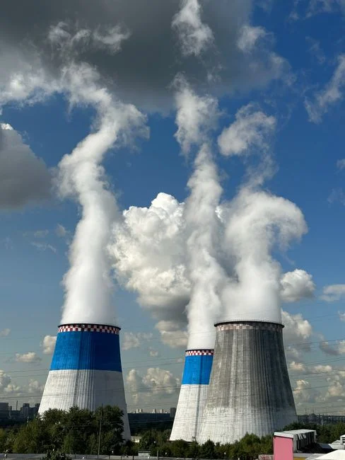
Commissioning must verify that the plant protects cooling reliability under normal and abnormal feed conditions. The acceptance programme should cover feed chemistry, treated-water quality, flow, recovery, energy consumption, chemical use, solids removal and automatic-control response.
Monitor risk-based parameters during operation. Flow and differential pressure support equipment condition checks; conductivity and pH indicate salt and acid–base changes; turbidity tracks solids carryover; residual disinfectant provides biological control; and silica, hardness and other cooling-critical parameters must remain within the agreed limits. Trends are more useful than isolated readings because gradual membrane fouling or source deterioration can otherwise reach the cooling system before an operator notices.
Johor’s April 2024 data centre guidelines encouraged operators to explore renewable water and energy supplies, according to The Straits Times in August 2025. The supplied research does not establish a universal discharge permit for a particular facility. Confirm site-specific discharge, abstraction and environmental obligations early with the relevant Johor and Malaysian authorities.
Provide segregated bypasses, adequate treated-water storage and contingency arrangements so a treatment interruption does not become a cooling outage. Automatic chemical dosing controls should be interlocked with water quality and flow signals. Operator training, membrane cleaning, cartridge replacement, disinfection verification and chemistry trending belong in the operating plan from commissioning onward.
Frequently Asked Questions
How should wastewater treatment capacity be sized for a Johor Bahru data centre?
Start with the cooling water balance: separate gross make-up, evaporation, drift and blowdown; establish cooling tower cycles of concentration; then credit reclaimed water and recovered blowdown. Check peak fill, cleaning outages, power loss, feed variability and loss of the external supply before assigning treatment redundancy. A headline litres-per-day figure should not replace site measurements.
Which treatment plant should be selected for reclaimed water or cooling blowdown?
Select the configuration from demonstrated feed chemistry and required cooling-water quality. UF addresses suspended solids and colloids but does not remove dissolved salinity; conventional BWRO may be appropriate after suitable pretreatment, while high-recovery blowdown treatment requires more complex scale and residual controls. Require supplier demonstrations against the actual feed limits and acceptance criteria.
What costs should a buyer include when comparing treatment quotations?
Compare source-water charges, energy, chemicals, membrane and cartridge replacement, operators, residual disposal and downtime. Also request quotations for the complete scope, including storage, controls, redundancy, commissioning and maintenance. The research provides no project price, so a defensible budget requires site flow, chemistry, recovery target, equipment basis and supplier quotations.
How should a buyer assess a treatment supplier’s suitability and compliance risk?
Check demonstrated feed-water limits, materials of construction, control philosophy, redundant pumps, membrane replacement, local service support, performance guarantees and acceptance tests. Confirm the destination and regulatory basis for concentrate, precipitate and sludge before award. The regional data center wastewater treatment guide illustrates why site-specific conditions must guide procurement rather than a generic package.
Should a data centre prioritise reclaimed sewage effluent or cooling tower blowdown recovery?
Prioritise external reclaimed water when a secure effluent supply can meet cooling chemistry after treatment, because it adds a controlled source while reducing municipal dependence. Evaluate internal blowdown recovery separately using silica, hardness, conductivity, chemical history and residual-handling constraints. The two options can be combined, but they require different feedwater analyses, equipment and acceptance tests.