Why wet processing equipment fails in the same handful of ways
The wet-processing train in a municipal or industrial wastewater plant — screening, grit removal, primary clarification or DAF, biological or MBR, membrane, disinfection and sludge dewatering — repeats the same failure physics at every station: particulate overload, emulsified or colloidal fouling, scaling, biofilm growth and air binding. An MBR tripping on high transmembrane pressure and a DAF discharging cloudy effluent are usually the same family of failure (upstream solids breakthrough plus chemistry drift) showing up in two different unit operations.
The FMEA framing in ASM International's Failure Modes and Effects Analysis treats every equipment failure as a triplet of effect, cause and detection. Two Elsevier studies on process-industry failures — the operations failure modes paper (doi 10.1016/j.jlp.2010.05.008) and the procedural execution failure modes paper (doi 10.1016/j.jlp.2011.06.007) — extend that triplet to human and procedural layers. The combined taxonomy gives three buckets used in the rest of this article: mechanical/structural (a rake tooth bent by a slug of rags), process/chemistry (coagulant dose drifting off setpoint after a pH probe fouled), and procedural/human (a CIP interval that quietly doubled because the operator who owned it left). Treating them as one list, rather than three separate problems, is what turns a parts catalogue into a usable register. A predictive layer on top of that register is covered in this 2026 engineering guide to predictive maintenance for wastewater plants.
Headworks screening and pumping: jams, overload trips and loss of prime
Headworks screens fail when their cleaning mechanism cannot keep up with rag and plastic load, and transfer pumps fail when the suction side of the train is no longer delivering the conditions the pump was specified for. The two are linked: a screen that bypasses rags hands those rags straight to the downstream pump.
On the screening side, the recurring modes are rake wrap, blinding between bars, an overload trip triggered by a slug of solids, brush-discharge failure that leaves debris on the downstream belt, and rag carryover that jams the transfer pump impeller. The HydropureWater GX rotary mechanical bar screen with dual overload protection ships with two independent overload trips and a self-cleaning brush discharge as designed-in mitigations, but those mitigations still need a visual inspection of rake teeth and brush wear on a fixed cadence to remain effective.
On the pumping side, the recurring modes are cavitation from a fouled suction screen (NPSH margin is lost long before the screen looks blocked), loss of prime from air ingress on intermittently operated pumps, mechanical-seal failure from running dry, and coupling or bearing failure from misalignment that shows up as elevated vibration. The prevention levers are straightforward: a documented NPSH-margin check at design review, a suction-side screen cleaning cadence tied to ΔP rather than the calendar, seal-flush water kept live during every pump run, and vibration plus bearing-temperature trending in the CMMS so a bearing fault is caught weeks before a coupling shears.
| Unit operation | Failure mode | Symptom | Root cause | Verification | Prevention |
|---|---|---|---|---|---|
| Bar screen | Rake blinding | Upstream level rising, rake cycling continuously | Rags/plastics exceeding design load | ΔP across screen, upstream level transmitter | Dual overload trip, brush discharge inspection, rag capture upstream |
| Bar screen | Overload trip | Unit offline, downstream pump rag-jammed | Single overload sensor failed silently | Test both overload channels on PM | Dual overload channels with independent wiring |
| Transfer pump | Cavitation | Noise, vibration, loss of flow | Suction screen fouled, NPSH margin gone | Suction-side ΔP, pump amp draw | Suction screen cleaning cadence tied to ΔP |
| Transfer pump | Loss of prime | Pump runs but no flow | Air ingress on intermittent duty | Air in seal-flush line, vacuum on suction | Seal-flush water always live during run |
| Transfer pump | Mechanical seal failure | Leak from seal area | Run-dry event | Seal-flush flow switch, bearing temp | Low-flow interlock to trip pump |
Clarification and flotation: cloudy effluent, scum overflow and air-binding

Clarifier and DAF failures are usually diagnosed as mechanical when the root cause is chemistry, and that misdiagnosis wastes most of the maintenance budget. The cheapest test is a jar test against current feed — if the jar clears and the DAF does not, the problem is hydraulic or mechanical; if neither clears, the chemistry is off.
DAF failure modes cluster around four signals: cloudy effluent from under-dosed coagulant, wrong pH window, or a hydraulic surge from upstream batch discharge; scum overflow when the skimmer cannot remove the float load or the float load itself has spiked; micro-bubble collapse from a saturator losing pressure or a recycle pump losing flow; and sludge buildup in the float chamber when downstream withdrawal is undersized. The HydropureWater DAF system (4–300 m³/h, automatic skimming) gives a documented operating envelope across 13 standard models that a maintenance team can compare against when the unit "suddenly can't keep up" — most of those complaints resolve to feed outside that envelope rather than equipment failure.
Lamella clarifier failures look different but have the same drivers: plate fouling from biological growth or oil, sludge recirculation failure that starves the plates of blanket, short-circuiting from a damaged inlet distribution baffle, and settled-solids carryover during peak flow events. The prevention levers are a jar-test cadence on the chemistry side, saturator pressure and recycle-ratio logs on the DAF side, a lamella plate wash schedule on a calendar that is not allowed to slip, and an equalization buffer sized against the worst upstream batch discharge the plant actually sees, not the one it was designed for.
| Unit operation | Failure mode | Symptom | Root cause | Verification | Prevention |
|---|---|---|---|---|---|
| DAF | Cloudy effluent | Turbidity > setpoint downstream | Coagulant under-dose, pH drift, hydraulic surge | Jar test, online pH and turbidity | Fixed jar-test cadence, flow-equalization buffer |
| DAF | Scum overflow | Floats spilling over effluent launder | Skimmer failure or float load spike | Skimmer torque, scum hopper level | Skimmer torque alarm, influent load trending |
| DAF | Micro-bubble collapse | Turbid effluent with no clear cause | Saturator pressure loss, recycle pump issue | Saturator pressure gauge, recycle flow | Saturator pressure log, recycle pump PM |
| Lamella | Plate fouling | Rising sludge blanket, carryover | Biofilm or oil on plates | Inspection port, NTU profile | Plate wash schedule, upstream oil removal |
| Lamella | Short-circuiting | Carryover during peak flow | Inlet baffle damaged, uneven distribution | Tracer study, surface NTU profile | Baffle inspection, equalization |
Membrane separation: fouling, scaling, fiber breakage and CIP drift
Membrane failure is the easiest unit operation to over-complicate. Almost every membrane failure is one of four modes: colloidal or organic fouling, scaling, mechanical breach, or a CIP interval that has quietly stretched beyond the recipe it was written for. Each maps to a measurable signal.
MBR failures show up as a rapid TMP climb driven by sludge bulking, MLSS run above design, or aeration scour failing because the aeration box blower or its diffusers have degraded. The HydropureWater DF series flat-sheet MBR module integrates an aeration box specifically to keep continuous scour air under the membrane, but the scour flow itself must be trended. UF failures are typically colloidal fouling or biofilm build-up when backwash and air-scour cadence slip, and integrity breach on a single fiber. The HydropureWater UF system with 0.03 μm PVDF membranes and automatic backwash is rated to 2,000–40,000 L/h and accepts feed up to 300 ppm turbidity — that envelope is the right baseline for whether a fouling event is a feed excursion or a maintenance miss. RO failures layer scaling (silica, CaCO₃) and biofouling on top of the same logic, plus O-ring and brine-seal failures on the pressure vessels and permeate-quality drift from a fouled conductivity probe.
Prevention levers: a feed-water SDI target on the upstream multi-media filter as a hard trip, a fixed CIP recipe and frequency that is enforced by the PLC rather than the operator, TMP and permeability trending with setpoint-driven CIP triggers, an integrity-test schedule, and a stocked consumables plan against the planned replacement interval — replacement HydropureWater cross-supplier-compatible RO and UF membrane elements held against the predicted swap date, not ordered when the train is already failing. Where biology alone cannot keep fouling under control, oxidation is an established lever per Water Intelligence Online's Chemical Oxidation Applications for Industrial Wastewaters (doi 10.2166/9781780401416). The full MBR membrane module design criteria for 2026 are covered in a separate engineering guide.
| Unit operation | Failure mode | Symptom | Root cause | Verification | Prevention |
|---|---|---|---|---|---|
| MBR | Rapid TMP climb | Permeability drop, aeration scour alarm | Sludge bulking, MLSS too high, scour failure | TMP, MLSS, scour airflow | MLSS setpoint, scour airflow trending, WAS rate |
| MBR | O-ring leak | Wet frame, aeration short-circuit | O-ring age or chemical attack | Visual on pull-down, leak detect | O-ring replacement at fixed interval |
| UF | Colloidal fouling | TMP rise between CIPs | SDI creep, CIP interval slipped | Feed SDI, TMP trend | SDI trip on upstream MMF, PLC-enforced CIP |
| UF | Fiber breach | Integrity test fail, turbidity creep | Mechanical damage, age | Pressure decay test | Scheduled integrity test, gentle startup ramp |
| RO | Scaling | Stage 2 ΔP rise, recovery drop | <>Silica, CaCO₃, antiscalant mis-doseConductivity profile, scale probe | Antiscalant dose verification, recovery cap | |
| RO | Biofouling | Permeate flow loss, salt passage rise | Biocide feed off, biofilm on membrane | ATP swab, normalized flow | Biocide SIP schedule, biocide skid interlocks |
Chemical dosing and disinfection: drift, under-dose and intensity loss
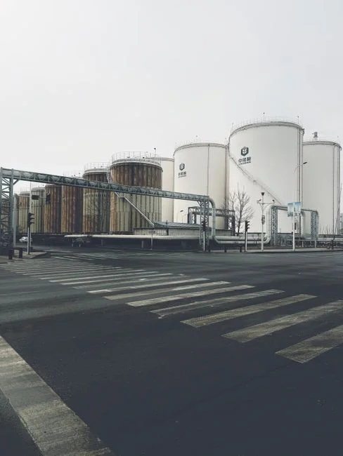
The single most common 2026 compliance failure in wet processing is chemistry that is still "running" but no longer hitting setpoint. The skid is powered, the pumps are stroking, the lamps are on — and the dose has quietly drifted below the validated window.
Dosing skid failure modes are a stuck diaphragm pump (one check valve failed), an air-locked suction line, a clogged injection quill, calibration drift on the stroke counter, wrong-strength chemical delivered by the supplier, and a day tank running dry with no low-level interlock to the SCADA. The HydropureWater PLC-controlled automatic chemical dosing skid addresses most of these with stroke-count verification, but a periodic bench calibration is still the only check that catches a pump that is stroking correctly at the wrong output. UV failures are quartz sleeve fouling, lamp end-of-life without a calibrated intensity sensor, ballast failure, flow exceeding the validated dose window, and turbidity spikes reducing UV transmittance. The UV sterilizer needs a calibrated intensity sensor and a logged lamp-hours counter, not just a green power light. ClO₂ and O₃ failures layer precursor-ratio drift on the generator, intensity sensor scaling, off-gas carryover and contact-tank short-circuiting on top of the same logic.
Disinfection failures carry direct compliance exposure. An under-dose on a HydropureWater ClO₂ generator (50 g/h–20,000 g/h, EPA / EU 98/83/EC / WHO compliant) sized within its envelope is a documentation and maintenance problem; an under-dose on a system that is out of envelope is a permit problem against EPA pretreatment rules, the EU Drinking Water Directive 98/83/EC, and the WHO Guidelines for Drinking-water Quality simultaneously. The procurement and injection side of the same problem is covered in the 2026 engineering guide to PLC-controlled chemical injection.
| Unit operation | Failure mode | Symptom | Root cause | Verification | Prevention |
|---|---|---|---|---|---|
| Dosing skid | Stuck diaphragm pump | Dose trend flat despite flow | Failed check valve, air lock | Stroke count vs bench dose | Stroke-count verification, periodic rebuild |
| Dosing skid | Calibration drift | Residual trending off setpoint | Pump output drifted, strength wrong | Bench titration | Quarterly bench calibration, chemical COA check |
| UV | Quartz sleeve fouling | Intensity alarm | Scale or biofilm on sleeve | Intensity sensor reading | Wiper or scheduled clean, online intensity trend |
| UV | Lamp end-of-life | Gradual intensity loss | Lamp hours exceeded, sensor uncalibrated | Lamp-hours counter, reference sensor | Replace at rated hours, calibrate sensor annually |
| ClO₂ | Precursor-ratio drift | Residual under setpoint | Acid or chlorite feed off-ratio | Generator telemetry, residual | Dual precursor pumps with stroke-count check |
| O₃ | Off-gas carryover | Ozone in off-gas, contact tank odor | Reaction-time shortfall, destructor fail | Off-gas monitor, contact tank level | Off-gas interlock, destructor PM |
Sludge dewatering: wet cake, cloth blinding and press cycle drift
"Wet cake" at a filter press is almost never a frame problem. It is a conditioning problem, a cloth problem, or an upstream biological problem that has propagated downstream. The frame and hydraulics are usually the last thing to fail.
Recurring failure modes on a plate and frame press are filter cloth blinding (polymer dose wrong, feed solids changed), cloth tearing (mechanical damage or age), hydraulic pressure not building (pump or seal failure), cycle time creeping longer as feed characteristics change, cake sticking to plates, and excessive filtrate solids pointing to torn cloth. The HydropureWater plate and frame filter press (1–500 m², PLC option) covers manual through fully automatic operation — the operating mode determines which failure modes are even visible to the operator, since a manual press cannot log cycle drift the way a PLC-controlled one can.
Prevention levers are a cloth wash-water pressure check on every shift, feed solids and polymer-dose trending against cake dryness, periodic cloth replacement on a meter-based interval rather than waiting for tears, and a hydraulic system inspection on the same cadence as the rest of the press. Sludge failures also propagate backward: bulking sludge or foaming in the bioreactor surfaces at the press first, which is why the upstream MLSS and F/M trending belong on the same review as the press log. Spares — cloths, polymer pumps, seals, valves — are covered in the HydropureWater parts, valves and media line.
| Unit operation | Failure mode | Symptom | Root cause | Verification | Prevention |
|---|---|---|---|---|---|
| Filter press | Cloth blinding | Cycle time lengthens, wet cake | Polymer dose off, feed solids up | Cake dryness, filtrate NTU | Polymer dose trending, cloth wash pressure check |
| Filter press | Cloth tearing | Excessive filtrate solids | Mechanical damage, age | Filtrate NTU, visual on cloth | Meter-based cloth replacement, visual PM |
| Filter press | Hydraulic pressure not building | Press stalls mid-cycle | Pump or seal failure | Hydraulic gauge, pump current | Hydraulic PM aligned with press PM |
| Filter press | Cycle time creep | Throughput drops, cake wetter | Feed solids or polymer drift | PLC cycle log | PLC cycle-time alarm, polymer calibration |
A 2026 failure-mode × prevention matrix you can copy into your CMMS
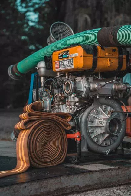
One consolidated matrix beats five station-by-station tables when the goal is a CMMS task list. The columns below are what a maintenance planner pastes into a failure-mode register; the rows are the same station list the previous sections walked through.
The detection-signal column reuses the same physical measurements (ΔP, TMP, NTU, SDI, dose, current, vibration) across the train, which is the practical insight: a plant can catch the majority of failure modes with a small sensor stack and a consistent trending dashboard, rather than instrumenting every failure mode individually. Design-margin choices on the equipment side are what make the PM task realistic — a UF rated to 300 ppm turbidity with auto backwash, a ClO₂ generator spanning 50 g/h–20,000 g/h, and a filter press from 1–500 m² give the maintenance planner headroom to set intervals that match the failure mode, not the worst-case feed.
| Unit operation | Failure mode | Root cause | Detection signal | Preventive action | Frequency | Owner |
|---|---|---|---|---|---|---|
| Bar screen | Rake blinding, overload | Solids/rag load | Upstream level, ΔP | Dual overload trip, brush PM | Daily walk-down, monthly trip test | Maintenance |
| Transfer pump | Cavitation, loss of prime | Suction screen fouled, air ingress | Suction ΔP, vibration, amp | ΔP-tied cleaning, seal-flush interlock | Continuous trend, weekly review | Reliability |
| DAF / Lamella | Cloudy effluent, scum overflow | Chemistry drift, hydraulic surge | NTU, pH, saturator pressure | Jar-test cadence, equalization | Per shift / weekly | Process |
| MBR / UF / RO | Fouling, scaling, breach | SDI creep, CIP slip, age | TMP, SDI, conductivity, integrity test | PLC-enforced CIP, SDI trip, integrity schedule | Continuous / quarterly | Process + Maintenance |
| Dosing / UV / ClO₂ / O₃ | Drift, under-dose, intensity loss | Calibration drift, sleeve scale, lamp age | Stroke count, residual, intensity | Bench calibration, lamp replacement, sensor cal | Quarterly / annual | Process + Compliance |
| Filter press | Wet cake, cloth blinding | Polymer drift, cloth age | Cycle time, cake dryness, filtrate NTU | Meter-based cloth change, polymer trending | Continuous trend, annual rebuild | Maintenance |
Plants that are ready to move from calendar-based to condition-based PM should layer this matrix onto the 2026 engineering guide to predictive maintenance for wastewater plants — the same detection signals become the inputs to a PdM model.
What to ask a wet-processing supplier before you buy the replacement
Most 2026 RFQs evaluate equipment on flow and price, then discover the failure modes the OEM knew about but did not document. The checklist below is what a maintenance team should send with every vendor bid, and what the answer should contain.
Ask for the unit's documented operating envelope — flow range, turbidity ceiling, pressure and temperature limits — so the bid can be compared against your worst-case feed, not your average feed. Ask for the failure modes the OEM has seen in the field, the trip and interlock list shipped with the PLC, and the recommended CIP or maintenance recipes with their expected intervals. Ask for the spares and consumables list with model numbers — membrane elements, filter cloth, lamps, chemicals, valves, filter media — and confirm cross-supplier compatibility against your existing HydropureWater cross-supplier-compatible RO and UF membrane elements and parts, valves and media. Finally, ask for the compliance envelope the equipment was designed against — EPA pretreatment rules, EU IED 2010/75/EU, EU Drinking Water Directive 98/83/EC, WHO Guidelines and the local pretreatment ordinance — so the design margin maps onto your actual discharge permit rather than a generic one.
Frequently Asked Questions
What counts as a "failure mode" in wet processing equipment, and how is it different from a fault or a defect?
A failure mode in the FMEA sense is the way an item fails to deliver its function — the effect — together with the cause and the detection signal. A fault is the immediate mechanical or process deviation; a defect is a manufacturing or installation issue. ASM International's FMEA methodology (Failure Modes and Effects Analysis) ties all three together, and the Elsevier process-industries studies on operations and procedural failure modes (doi 10.1016/j.jlp.2010.05.008 and 10.1016/j.jlp.2011.06.007) extend that framing to procedural and human layers. In a wet-processing train the failure mode is what you write into the CMMS — for example, "DAF cloudy effluent caused by coagulant under-dose, detected by downstream NTU trend" — and that triplet is what the prevention task is built against.
How do I pick the right size UF or RO system so I don't design it into a fouling failure on day one?
Size the unit against your worst-case feed, not your average feed. The inputs you must obtain from the OEM and from your own plant data are: feed SDI (the Silt Density Index after the upstream multi-media filter), peak feed turbidity, target recovery, target permeate flux and the CIP recipe the OEM recommends at those conditions. A UF rated to 300 ppm turbidity with automatic backwash, or an RO whose membrane elements are stocked for your planned replacement interval, gives you the headroom to operate inside a realistic PM cadence. Without those numbers the system will be undersized the first time the upstream process drifts.
What line items should be in a 2026 wet-processing equipment budget beyond the skid price?
The consumables and service line that most budgets miss. For a UF/RO train the items are membrane elements, CIP chemicals, cartridge filters and instrument calibration; for a filter press they are filter cloth, polymer, hydraulic seals and the PLC option that turns cycle drift into a visible trend; for UV they are lamps, quartz sleeves and intensity sensor calibration; for ClO₂ they are precursor chemicals, generator maintenance and intensity verification. The full parts, valves and media line is at HydropureWater parts, valves and media. A reasonable 2026 budget request to a vendor should ask for unit price, recommended replacement interval and annual consumable cost together — not as three separate RFQs.
How do I compare wet-processing equipment suppliers on reliability, not just price?
Ask for four documents. First, the failure modes the OEM has seen in the field and how the PLC interlocks respond to each. Second, the shipped trip and interlock list with the rationale for each setpoint. Third, the spares and consumables list with model numbers, plus a written statement on cross-supplier compatibility — relevant for membrane elements in particular, where a single supplier lock-in becomes a reliability risk. Fourth, the compliance evidence: which EPA, EU IED 2010/75/EU, EU Drinking Water Directive 98/83/EC and WHO Guidelines the unit was designed and tested against. A supplier that cannot produce all four should be scored down regardless of skid price.
Which failure modes create the biggest compliance risk under 2026 pretreatment and reuse rules, and how do I prioritize them?
Disinfection and membrane integrity failures are the priority list, because they map directly onto permit limits rather than onto internal KPIs. An under-dose on UV or ClO₂ that lets total coliform or ClO₂ residual breach the limit is a non-compliance event under EPA pretreatment, EU Drinking Water Directive 98/83/EC and the WHO Guidelines for Drinking-water Quality simultaneously. A UF integrity breach or an RO conductivity excursion creates the same exposure on a reuse permit, and on a discharge permit for total dissolved solids or specific contaminants. Prioritize these in the register with a hard PLC interlock, not a soft alarm, and review them on a faster cadence than mechanical-only failure modes.
Related Equipment
- HydropureWater MBR membrane bioreactor with submerged PVDF filtration — specifications, capacity range, and technical data