What Counts as Ultrapure Water in a US Semiconductor Fab
Ultrapure water (UPW) in a US semiconductor fab is defined as water with resistivity of 18.2 MΩ·cm at 25°C — the theoretical maximum for pure H₂O — paired with total organic carbon (TOC) below 1 ppb, dissolved oxygen below 1 ppb, particles larger than 0.05 µm held below 0.3 particles/mL, and bacteria below 1 CFU/100 mL. These numbers are not aspirational; they are the operating envelope a leading-edge fab designs to and continuously measures inline. Resistivity of 18.2 MΩ·cm means effectively zero dissolved ions, which matters because even sub-ppb metal contamination (Cu, Fe, Na) on a wafer surface produces junction leakage, DRAM retention failure, and gate-oxide integrity loss (per SEMI F63, 2026 revision). At 3 nm and 2 nm nodes, the TOC spec tightens to below 0.5 ppb because organic compounds contaminate EUV optics and interfere with gate dielectric formation (per AXEON, 2026).
Three governing specifications define the envelope: SEMI F63 for semiconductor process water, ASTM D5127 for electronics and semiconductor UPW, and ISO 3696 Grade 1 for the highest laboratory water classification. Each fab's quality group maintains a contamination budget that ties every parameter to a defect-density yield model — if resistivity drifts to 18.0 MΩ·cm for any sustained period, the operations team responds before the metrology group sees excursion on a wafer.
| Parameter | UPW specification | Measurement method |
|---|---|---|
| Resistivity | >18.2 MΩ·cm at 25°C | Inline conductivity meter |
| TOC | <1 ppb (current nodes); <0.5 ppb at 2 nm/3 nm | UV-persulfate oxidation |
| Particles (>0.05 µm) | <0.3 particles/mL | Laser particle counter (per SEMI F63) |
| Dissolved oxygen | <1 ppb | Membrane contactor + inline DO probe |
| Bacteria | <1 CFU/100 mL | Membrane filtration, R2A agar |
| Silica (dissolved) | 0.2–1.0 ppb | ICP-MS |
| Silica (colloidal) | 0.3–2.0 ppb | ICP-MS |
| Metals (Cu, Fe, Na, K) | Sub-ppb each | ICP-MS |
How Much Water a US Fab Actually Pulls and Recycles
A leading-edge 300 mm fab (N3–N5) draws 10–20 MGD of municipal water to feed its UPW train and recycles 30–80% of that volume back into the process, putting net withdrawal in the 2–10 MGD range (per SemiconductorX, 2026). That is a small-city utility demand sitting inside a single utility building. Each 200 mm wafer requires roughly 5,600 L of UPW for cleaning; advanced fabs run 4.5–7 L of UPW per cm² of processed wafer, and that intensity rises with process complexity — more CMP steps, more wet etches, more cleaning sequences at advanced nodes. The municipal feed ratio runs 1,400–1,600 gallons of city water per 1,000 gallons of UPW produced, with the difference lost to RO reject, cooling tower drift, and backwash (per AXEON, 2026).
Best-in-class reuse sits at 50–80%, with Intel Oregon above 80% in published sustainability reports and TSMC committed to 100% recycling at Arizona Fab 21 (per SemiconductorX, 2026). For a 2026 bid, treat 65–75% as the working assumption and design the recycle loop to allow the site to climb toward 90% without major retrofit. Rinse water dominates the recycle volume; RO concentrate, cooling-tower blowdown, and CMP slurry dominate the waste volume. CHIPS Act fabs in Arizona and Texas face Colorado River and Edwards Aquifer constraints that force recycling targets above the Taiwan baseline — water rights allocations are measured in acre-feet per year, so even a 2–5 MGD net withdrawal is a politically significant draw on the watershed.
The Six-Stage UPW Treatment Train
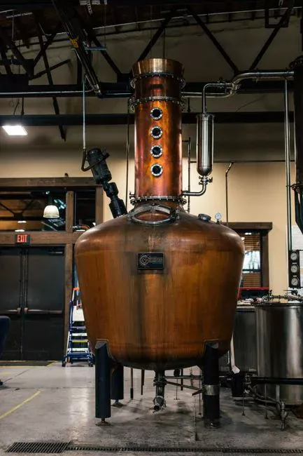
UPW is the output of a six-stage train in which each stage removes a specific contaminant class to progressively higher purity. The design must account for source-water quality, required throughput, and the distribution loop — UPW quality degrades in piping if it is not continuously recirculated and re-purified, which is why a UPW system is a continuous-operation facility in its own right, typically housed in a dedicated utility building adjacent to the fab proper.
Stage 1 — Pretreatment. Multimedia filtration, activated carbon, and sodium-cycle softening drop turbidity below 0.1 NTU, chlorine below 0.1 ppm, and hardness below 1 ppm as CaCO₃. This stage protects downstream RO membranes from fouling and oxidation. Multi-media pretreatment ahead of two-pass RO is the conventional US install. Stage 2 — Two-pass RO. Spiral-wound polyamide thin-film composite membranes at 150–300 psi reject 95–99% of dissolved ions. One pass delivers 0.5–2 MΩ·cm; the second pass pushes resistivity to 1–5 MΩ·cm and removes the bulk ionic load for downstream polishing. An industrial RO system for two-pass UPW production is sized for 70–85% recovery per pass, with the concentrate routed to wastewater treatment. Stage 3 — EDI. A DC field drives residual ions through cation and anion exchange membranes to deliver 15–17 MΩ·cm and silica below 5 ppb without acid or caustic regeneration, which is the operational advantage over conventional mixed-bed DI. Chemical-free EDI polishing for 15–17 MΩ·cm UPW output replaces the regeneration cycle of a traditional mixed-bed with continuous electrical regeneration. Stage 4 — UV oxidation. 185 nm lamps reduce TOC to below 1 ppb by oxidizing dissolved organics to CO₂; 254 nm sterilizes bacteria and endotoxins. Downstream CO₂ degassing is required to remove the oxidation byproduct before it reaches the polishing loop. A 185/254 nm UV stage for TOC reduction and bacteria control is typically specified with 9,000–12,000-hour lamp life. Stage 5 — Vacuum or membrane degassing. Hollow-fiber membrane contactors (3M Liqui-Cel, Membrana) drive dissolved O₂ below 1 ppb to prevent native oxide growth on silicon during cleaning; a vacuum on the shell side with nitrogen sweep is the standard configuration. Stage 6 — Mixed-bed DI + UF polishing. Final ionic polishing on mixed-bed resin drops residual ions below 0.1 ppb; 0.03 micron UF polishing for the UPW distribution loop removes particles at point of use under continuous recirculation. A real fab typically feeds the train with a blend of reclaimed wastewater and municipal supply to reduce Colorado River demand at Phoenix or Taylor sites.
| Stage | Equipment | Removes | Output / setpoint |
|---|---|---|---|
| 1 Pretreatment | Multi-media filter, activated carbon, softener | Turbidity, chlorine, hardness | Turbidity <0.1 NTU; Cl₂ <0.1 ppm |
| 2 Two-pass RO | Spiral-wound polyamide, 150–300 psi | 95–99% dissolved ions, bacteria, colloids | 0.5–2 MΩ·cm after 1st pass; 1–5 MΩ·cm after 2nd |
| 3 EDI | Cation/anion membranes, DC field | Residual ions, silica | 15–17 MΩ·cm; SiO₂ <5 ppb |
| 4 UV oxidation | 185 nm + 254 nm lamps | TOC, bacteria | TOC <1 ppb; <1 CFU/100 mL |
| 5 Degassing | Hollow-fiber contactor or vacuum tower | Dissolved O₂, CO₂ | DO <1 ppb |
| 6 Mixed-bed DI + UF | Cation + anion resin; 0.02–0.05 µm UF | Residual ions, particles | 18.2 MΩ·cm; <0.3 particles/mL (>0.05 µm) |
Fab Wastewater: Why the Drain Streams Must Stay Segregated
Used process water from a fab is not one stream but five chemically incompatible streams that must be segregated at the point of generation and treated separately before recycle or discharge. The segregation is engineered into the fab drain system from day one — mixing HF with alkalis or slurry with acid creates hazardous conditions and complicates treatment, and that is a hard design constraint rather than a soft preference (per SemiconductorX, 2026). Each stream drives a different downstream treatment train and a different recycle economics, which is why wastewater and UPW design have to be co-developed from process-flow lock.
Rinse water carries trace ions, low TOC, and low particle load — the cleanest fab drain and the primary source of recycle volume. After UF polishing it can re-enter the UPW polishing train directly. Acid waste from HF, H2SO₄, HCl, HNO₃ etching carries fluoride and metal ions; it is neutralized with caustic, then calcium fluoride is precipitated to pull fluoride out before discharge. Fluoride contamination limits recycle economics. Alkaline waste from NH₄OH, H₂O₂, and TMAH developer goes through ammonia stripping and biological TMAH degradation, with NPDES limits on ammonia and TMAH. CMP slurry waste carries SiO₂, CeO₂, Al₂O₃ particles plus Cu, W, and barrier metals; filter press dewatering of CMP solids produces a hazardous-waste solid and a liquid stream routed to metal precipitation. RO concentrate carries the rejected salts and antiscalants from the UPW train; another RO pass plus evaporation or zero-liquid discharge (ZLD) reduces volume, and ZLD on cooling-tower blowdown is now standard at water-stressed Arizona sites. Solids flotation and metal hydroxide settling upstream of the filter press are commonly handled by a dissolved air flotation unit for CMP wastewater clarification.
| Drain stream | Key contaminants | Treatment | Recycle potential |
|---|---|---|---|
| Rinse water | Trace ions, low TOC, low particles | UF polish, return to UPW train | High — primary recycle volume |
| Acid waste (HF, H₂SO₄, HCl) | Fluoride, metal ions | Neutralization, CaF₂ precipitation, pH 6–9 | Low — fluoride limits reuse |
| Alkaline waste (NH₄OH, TMAH, H₂O₂) | Ammonia, TMAH, dissolved metals | NH₃ stripping, biological TMAH, metal precipitation | Low — NPDES discharge typical |
| CMP slurry waste | SiO₂, CeO₂, Al₂O₃, Cu, W | Flocculation, sedimentation, filter press | Very low — solids are hazardous |
| RO concentrate | High TDS, antiscalants, biocides | Second-pass RO, evaporation, ZLD | Moderate — ZLD enables near-zero discharge |
US CHIPS Act Fab Water Scorecard (2026)
Power and water are the two binding physical constraints on fab site selection. For the current CHIPS Act buildout, water is arguably the more geographically limiting of the two — power can be transmitted, but a 2–10 MGD net withdrawal requires a local watershed capable of sustaining that draw indefinitely through drought years. The scorecard below pairs each announced US fab with its source, watershed risk class, and recycling commitment so EPC teams can match site selection to water availability, not just to power interconnection or land cost.
| Fab / site | Water source | Watershed stress | Recycling / sustainability commitment |
|---|---|---|---|
| TSMC Arizona Fab 21 (Phoenix) | City of Phoenix + Central Arizona Project (Colorado River) + Salt River Project reclaimed water | Extreme — Sonoran Desert; Lake Mead / Powell at historic lows | 100% recycling; ZLD on cooling-tower blowdown (per SemiconductorX, 2026) |
| Intel Ohio (New Albany) | Columbus municipal + Licking County groundwater + Big Walnut Creek | Low–moderate — Ohio River basin, no shortage risk | Net positive water use; returns more than withdrawn (per SemiconductorX, 2026) |
| Intel Oregon (Hillsboro) | Tualatin Valley Water District + Tualatin River | Low — Pacific Northwest, abundant precipitation | >80% reuse; net positive water in published reports (per SemiconductorX, 2026) |
| Samsung Taylor (Texas) | City of Taylor + Little River / Brazos basin + Granger Lake | Moderate — central Texas drought cycles | Reclaimed water for cooling; Williamson County partnership (per SemiconductorX, 2026) |
| Micron Clay (New York) | Onondaga County Water Authority + Oneida Lake / Oswego River | Low — Great Lakes basin proximity, abundant supply | Favorable supply paired with NYPA hydropower (per SemiconductorX, 2026) |
UPW Equipment Suppliers, CAPEX, and 2026 Design Checklist
UPW system CAPEX sits in the $200–500M range for a leading-edge fab, with the recycle system adding $50–150M on top (per SemiconductorX, 2026). Both are treated as long-lead procurement items in fab construction scheduling — RO membranes, EDI stacks, and UF modules carry 12–18 month lead times on US projects in 2026, so the procurement clock starts during site due diligence rather than after groundbreaking. The dominant UPW system integrators are Evoqua (Xylem, with the Ionpure EDI line), Kurita, and Veolia. Key component suppliers are DuPont Water Solutions (FilmTec RO membranes) and Toray (RO and UF membranes), with HydropureWater supplying the pretreatment, RO, EDI, UV, UF, multi-media, and sludge-handling unit operations that integrate into any of the major integrator trains. For a tighter scope on consumables and spare parts, specify RO and UF membrane replacement elements and valves, instruments, and filter media for the UPW system as separate procurement packages rather than burying them in the integrator scope.
2026 design checklist for a US fab UPW project: lock the source-water profile and seasonal variability before sizing the train; size for 10–20 MGD gross feed with a 30–80% recycle target and a documented glide path to 90%; design segregated drain streams (rinse, acid, alkaline, CMP, RO concentrate) into the fab drain system from day one rather than retrofitting; specify ZLD on cooling-tower blowdown for any Arizona, Texas, or other water-stressed site; plan PLC-based continuous monitoring for resistivity, TOC, particles, and DO with alarm setpoints tied to the contamination budget; reserve space for a second-pass RO skid, additional EDI capacity, and a third RO train on the concentrate stream to climb the recycle rate without a shutdown. For a broader comparison of fabs outside the US, see UPW system specifications for UK semiconductor fabs; for the engineering behind the polishing loop, see polishing loop technologies for 18.2 MΩ·cm and sub-ppb TOC; for the yield-link logic behind these numbers, see the 2026 UPW contamination budget and defect-yield link.
Frequently Asked Questions
How much water does a US semiconductor fab use per day?
A leading-edge 300 mm fab (N3–N5) draws 10–20 MGD of municipal water to feed its UPW train. With 30–80% recycling, net withdrawal lands at 2–10 MGD — a small-city utility demand inside a single utility building (per SemiconductorX, 2026).
What is the UPW resistivity spec for a current US fab?
18.2 MΩ·cm at 25°C, the theoretical maximum for pure H₂O, paired with TOC below 1 ppb (tightening to below 0.5 ppb at 2 nm and 3 nm nodes), particles above 0.05 µm held below 0.3 particles/mL, and dissolved oxygen below 1 ppb (per SEMI F63 and AXEON, 2026).
What recycling rate should a 2026 US fab target?
Plan for 65–75% as the working assumption and design the loop to climb toward 90% without major retrofit. Intel Oregon is above 80% in published reports, and TSMC has committed to 100% recycling at Arizona Fab 21 (per SemiconductorX, 2026).
Which US CHIPS Act sites face the most watershed stress?
TSMC Arizona Fab 21 in Phoenix is the most constrained — Colorado River allocations through the Central Arizona Project, with Lake Mead and Lake Powell at historic lows. Samsung Taylor in central Texas is moderate; Intel Oregon, Intel Ohio, and Micron Clay sit in low-stress watersheds (per SemiconductorX, 2026).
What is the CAPEX range for a US fab UPW system in 2026?
$200–500M for the primary UPW system and $50–150M for the recycle system on top, treated as a long-lead procurement item with 12–18 month lead times on RO membranes, EDI stacks, and UF modules (per SemiconductorX, 2026).