Effluent Treatment Plant in Manchester: 2026 Buyer's Engineering Guide
An effluent treatment plant in Manchester for 2026 is typically a packaged MBR + DAF + UV train sized at 10–2,000 m³/day to meet United Utilities trade-effluent consent limits, the EU Urban Waste Water Treatment Directive (91/271/EEC) standards, and Environment Agency permit conditions. Manchester's textile, food, pharmaceutical and metal-finishing sectors see influent BOD of 250–1,800 mg/L and COD 500–4,000 mg/L, so designers combine biological MBR (<1 µm permeate) with DAF for fats/oils and a polishing stage before sewer or water-reuse discharge.
How Manchester's 2026 Consent Framework Shapes ETP Design
United Utilities enforces trade effluent chemical oxygen demand (COD) limits as low as 800 mg/L and total suspended solids (TSS) limits below 300 mg/L for sewer discharges across Greater Manchester in 2026 (source: United Utilities trade-effluent guidelines). Any industrial facility operating an effluent treatment plant in Manchester must secure a Trade Effluent Consent under Section 118 of the Water Industry Act 1991. These consent parameters are calculated using the regional Mogden Formula, which heavily penalises chemical oxygen demand and suspended solids. For direct environmental discharge, the Environment Agency (EA) aligns its permits with the EU Urban Waste Water Treatment Directive 91/271/EEC, requiring stringent limits of 125 mg/L for COD and 25 mg/L for biological oxygen demand (BOD).
When designing systems for water recycling or reuse, engineers must target the EU Drinking Water Directive 98/83/EC as a benchmark. Research from the University of Manchester highlights that conventional secondary activated sludge processes fail to eliminate complex organic compounds. Secondary effluent still carries significant micropollutant loads, with 17β-estradiol alone contributing approximately 97% of freshwater ecotoxicity potential at 1,700.8 CTUe per 1,000 m³ (source: University of Manchester LCA study). Consequently, EA inspectors increasingly expect newly commissioned plants to incorporate advanced polishing to mitigate ecotoxicological risks.
For municipal and industrial textile clusters in Greater Manchester, hydraulic head and flow balance are critical. Sizing analogues drawn from historical textile processing hubs show that managing a 12 MLD flow across multiple production lines requires a minimum hydraulic head of 4.8 metres to maintain gravity flow through primary screens and distribution channels without excessive pumping energy (source: IJRET Ichalkaranji CETP study). This makes equalization tanks and precise head-loss calculations essential during the initial layout phase of any Manchester-based industrial wastewater treatment Greater Manchester project.
Typical Manchester Influent Profiles by Industry
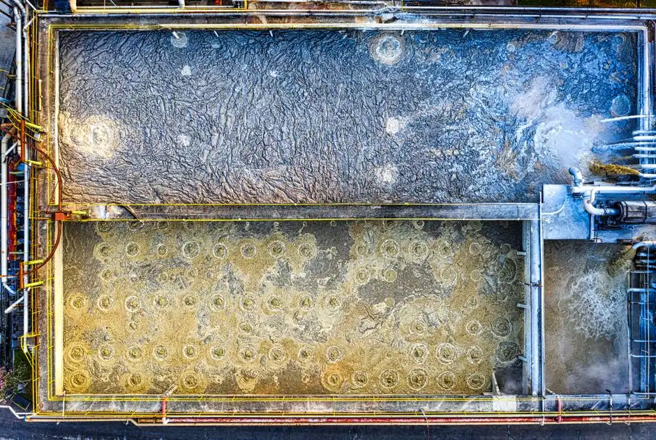
Industrial wastewater in Greater Manchester's manufacturing corridors varies from high-strength textile dyehouse effluent with COD up to 4,000 mg/L to food processing washwater containing up to 1,500 mg/L of fats, oils, and grease (FOG). To design an effective treatment system, process engineers must characterise raw influent before selecting physical, chemical, or biological stages. Sizing specifications must accommodate both peak hydraulic surges and concentrated chemical spikes common in batch processing.
Textile finishers in the region generate highly coloured, high-temperature (up to 45°C) wastewater with fluctuating pH levels from 5.0 to 10.5. Food and beverage processors face strict FOG limits from United Utilities, requiring robust physical pre-treatment. For these applications, installing a dissolved air flotation unit capable of handling 4 to 300 m³/h is necessary to lower the organic loading before it reaches biological reactors. In the pharmaceutical sector, active ingredients and ammonia (20–80 mg/L) require a combination of membrane bioreactors and advanced oxidation to break down complex molecular chains. The table below outlines typical raw influent parameters across the four dominant manufacturing sectors in Greater Manchester:
| Industrial Sector | BOD (mg/L) | COD (mg/L) | TSS (mg/L) | FOG (mg/L) | pH Range | Typical Temp (°C) |
|---|---|---|---|---|---|---|
| Textile Finishing | 250–1,800 | 1,000–4,000 | 300–1,200 | <50 | 5.0–10.5 | 30–45 |
| Food & Beverage | 600–2,000 | 1,200–5,000 | 400–1,500 | 150–1,500 | 4.5–9.5 | 15–30 |
| Pharmaceutical CMO | 150–800 | 800–2,500 | 100–500 | <10 | 6.0–9.0 | 20–35 |
| Metal Finishing | <50 | 150–600 | 200–800 | 50–300 | 2.0–11.0 | 15–25 |
Choosing the Right Process Train: DAF, MBR, UF or Hybrid
Membrane bioreactors operating with submerged PVDF membranes at a 0.1 µm nominal pore size achieve up to 99% BOD removal while reducing the physical footprint of an effluent treatment plant in Manchester by up to 60% compared to conventional activated sludge systems. Selecting the correct process train depends on raw contaminant concentrations, flow variability, and the desired discharge route. Designers must evaluate the trade-offs between capital expenditure and operational costs, particularly regarding energy consumption and chemical dosing.
The decision framework is governed by clear influent thresholds. If raw TSS exceeds 400 mg/L or FOG is greater than 200 mg/L, a DAF pre-treatment stage must be positioned upstream to protect biological membranes from fouling. For sites experiencing flow variability greater than 3:1, an MBR system provides superior process stability over conventional activated sludge due to its ability to maintain high mixed liquor suspended solids (MLSS) concentrations. When water reuse is the goal, incorporating a PVDF ultrafiltration system (rated at 2,000 to 40,000 L/h) or a downstream nanofiltration stage is required.
While nanofiltration (NF) produces high-purity water, it is energy-intensive. Life cycle assessment data indicates that 65% of nanofiltration's environmental impact stems from grid electricity consumption, which ranges from 150 to 1,300 kWh per 1,000 m³ of treated effluent (source: University of Manchester LCA Table S6). For sites seeking lower energy consumption, using a DF series flat-sheet MBR module (with surface areas of 80 to 225 m² and 0.1 µm pore size) provides a gravity-driven filtration option that reduces energy requirements by 10 to 20 times compared to external cross-flow membrane loops. The table below compares these primary process technologies:
| Technology | TSS Removal (%) | BOD Removal (%) | FOG Removal (%) | Footprint Requirement | Energy Consumption |
|---|---|---|---|---|---|
| Dissolved Air Flotation (DAF) | 70–90% | 30–50% (particulate) | 85–95% | Medium | Low (0.1–0.3 kWh/m³) |
| Membrane Bioreactor (MBR) | >99% | 95–99% | >99% | Very Compact | Medium-High (0.8–1.5 kWh/m³) |
| Ultrafiltration (UF) | >99% | N/A (physical only) | >99% | Compact | Medium (0.4–0.8 kWh/m³) |
| Nanofiltration (NF) | >99.9% | N/A (dissolved organics) | >99.9% | Compact | High (1.5–3.5 kWh/m³) |
Designing the Four-Stage Train for a 200 m³/day Manchester Plant
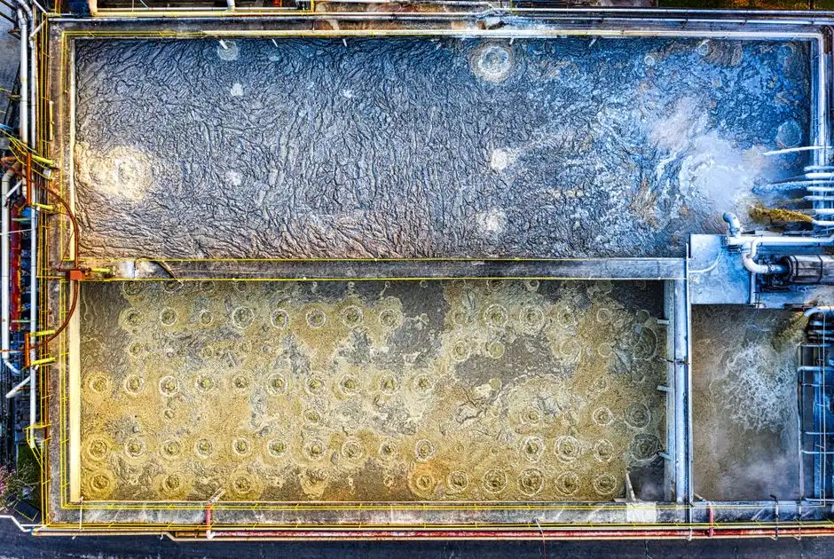
Sizing a packaged effluent treatment plant in Manchester for a nominal flow of 200 m³/day requires a peak hydraulic design capacity of 25 m³/hour to buffer diurnal manufacturing discharge surges. To achieve reliable compliance with United Utilities trade-effluent consent Manchester, a four-stage treatment train is standard. This configuration balances physical separation, biological digestion, membrane filtration, and final disinfection within a compact footprint.
The process begins with Stage 1 (Screening), where a rotary mechanical bar screen removes solids larger than 3 mm to protect downstream pumps and aeration systems. Stage 2 (Pre-treatment) utilizes a dissolved air flotation unit operating at a hydraulic loading rate of approximately 8 m³/hour. This stage removes 70–90% of FOG and 50–80% of suspended solids, utilizing a PLC-controlled chemical dosing skid to inject coagulants and flocculants automatically based on real-time flow rates.
Stage 3 (Biological Treatment and Filtration) is performed by a packaged HydropureWater MBR membrane bioreactor. This system operates at an MLSS concentration of 8 to 10 g/L (8,000 to 10,000 mg/L) to biological digest dissolved organic pollutants, yielding a high-clarity permeate with a turbidity under 0.2 NTU. Finally, Stage 4 (Disinfection and Polishing) routes the permeate through a pipeline UV steriliser to achieve pathogen log-reductions before discharge. For pharmaceutical or chemical manufacturing facilities with complex biocidal compounds, a chlorine dioxide generator is integrated as a secondary disinfection line to maintain compliance with World Health Organisation (WHO) and Environment Agency guidelines.
Sludge handling is managed via automated wasting. Excess biomass from the MBR and float material from the DAF are pumped to a sludge conditioning tank before being dewatered using a plate and frame filter press (sized from 1 to 500 m²). This dewatering process produces a dry cake with 30–35% dry solids (DS), significantly reducing off-site disposal volumes and haulage costs.
Advanced Polishing: When Nanofiltration or Ozonation Are Worth It
Nanofiltration operating at pressures between 5 and 15 bar achieves a 30% greater reduction in freshwater ecotoxicity compared to conventional secondary treatment by removing recalcitrant pharmaceutical residues down to a 0.1 nm molecular cutoff. For most industrial operations discharging directly to United Utilities sewers, an MBR system provides sufficient treatment. However, when plants must comply with strict direct-discharge permits or target zero liquid discharge (ZLD) through water recycling, advanced polishing stages become necessary.
According to life cycle assessment data, direct nanofiltration reduces the freshwater ecotoxicity potential of treated effluent to 1,157.3 CTUe per 1,000 m³ (source: University of Manchester LCA study). This is 30% lower than the minimum ecotoxicity of secondary effluent discharged without advanced polishing. However, this level of treatment requires 150 to 1,300 kWh of grid electricity per 1,000 m³ of water treated, alongside a chemical demand of 60 to 80 kg of sodium hydroxide per 1,000 m³ for pH adjustment and membrane cleaning. Ozonation is another option, operating at a transfer efficiency of 25% to 75% with an ozone dosage of 0.004 to 0.168 kg/m³. While ozonation is highly effective for colour removal in textile wastewater, it requires significant capital investment for ozone generators and destruction units.
Where nanofiltration is not financially viable, granular activated carbon (GAC) serves as a reliable alternative. GAC systems require a bed service time of 110 to 330 days at an empty bed contact time (EBCT) of 20 to 40 minutes, depending on the organic load (source: University of Manchester LCA inventory). With a bulk density of 564 kg/m³, GAC systems require a fresh carbon makeup of 5 to 22 kg per 1,000 m³ of treated wastewater, making them a practical choice for removing trace organics without the high electrical demands of membrane-based polishing.
2026 Cost Bands, Footprint and Energy Use
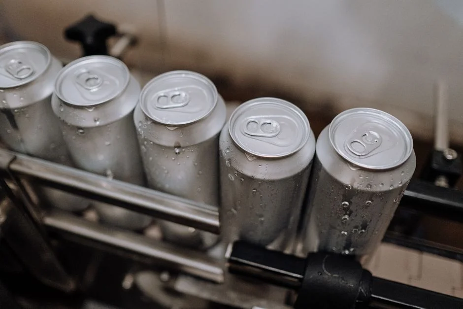
Capital expenditure for a containerised industrial effluent treatment plant in Manchester scales from £85,000 for a 10 m³/day system up to £1.2 million for a fully integrated 2,000 m³/day MBR and DAF train. Sizing, technology selection, and municipal sewer discharge fees all influence these financial projections. For small-scale applications, a WSZ underground packaged sewage plant (handling 1 to 80 m³/hour) provides a cost-effective, low-footprint option that minimizes site civil works.
Operating costs (OPEX) are driven by power consumption, chemical dosing, membrane replacement, and sludge disposal. Implementing a DF series flat-sheet MBR module can lower energy costs by reducing the aeration energy required to scour membrane surfaces. Additionally, using a plate and frame filter press to achieve a 30% dry solids cake reduces sludge disposal costs compared to liquid sludge hauling. Sizing calculations and cost projections from the University of Twente's membrane filtration research provide a benchmark for these operational parameters (source: University of Twente NF thesis). The table below outlines typical budget estimates for 2026 industrial projects:
| Plant Capacity (m³/day) | Primary Technologies | Est. CAPEX Range (£) | Est. OPEX (£/m³ treated) | Footprint (m²) | Average Power (kW) |
|---|---|---|---|---|---|
| 10 to 50 | Packaged MBR | 85,000 – 180,000 | 1.20 – 1.80 | 15 – 30 | 3.5 – 7.5 |
| 100 to 200 | DAF + MBR + UV | 220,000 – 450,000 | 0.85 – 1.40 | 40 – 80 | 12.0 – 22.0 |
| 500 to 1,000 | DAF + MBR + UF + Press | 650,000 – 950,000 | 0.65 – 1.10 | 120 – 250 | 45.0 – 85.0 |
| 2,000+ | Custom DAF + MBR + NF | 1,200,000 – 2,400,000 | 0.50 – 0.95 | 450 – 900 | 150.0 – 280.0 |
For comparative regional compliance standards, engineers may also refer to the Birmingham 2026 ETP buyer's guide or the London 2026 ETP buyer's guide. Detailed capital expenditure calculations for membrane systems are available in our MBR sewage cost price 2026 guide, while smaller municipal projects can reference the Birmingham 2026 domestic sewage compliance guide.
Frequently Asked Questions
What is the typical footprint of a 100 m³/day packaged MBR plant in Manchester?
Sizing a 100 m³/day plant using a containerised HydropureWater MBR membrane bioreactor requires approximately 30–45 m² of ground space, representing a 60% footprint reduction over conventional activated sludge clarifiers.
How does a DAF pre-treatment system protect downstream biological processes in food manufacturing?
A dissolved air flotation unit removes up to 90% of fats, oils, and grease (FOG) and 80% of suspended solids, preventing membrane fouling and biomass smothering in downstream MBR systems.
What are the energy requirements for upgrading to nanofiltration for water reuse?
According to University of Manchester LCA data, direct nanofiltration requires 150 to 1,300 kWh of grid electricity per 1,000 m³ of treated effluent, depending on operating pressures and fouling rates.
Can underground treatment systems be used for restricted-space Manchester sites?
Yes, the WSZ underground packaged sewage plant handles flows from 1 to 80 m³/hour, completely burying the biological reactor to eliminate surface footprint and odor concerns.