Why Refinery Wastewater Needs Ultrafiltration, Not Just Gravity Separation
Refinery process wastewater carries free oil, emulsified oil with droplets below 20 µm, total suspended solids (TSS) in the 100-500 mg/L range, COD of 300-800 mg/L, plus phenols, sulfides, and trace hydrocarbons from desalter, sour-water, and spent-caustic streams. Conventional plate separators, CPI units, and DAF cells only remove free oil droplets above roughly 150 µm — they pass the emulsified fraction and fine TSS through largely intact. That residual load is what blinds downstream sand filters within hours, and what fouls RO membranes irreversibly if it reaches them. The 2025 process-modelling study on a real industrial refinery confirmed this gap: the existing plate-separator + mixing + coagulation/flocculation + DAF train (their Scenario 1) underperforms against reuse and zero-discharge key performance indicators, and the authors conclude that fit-for-purpose advanced treatment — specifically an advanced train placed after the existing DAF — is required to close the water loop (Hu et al., 2025).
Ultrafiltration is that missing step. Operating at 0.01-0.1 µm pore size, UF physically rejects emulsified oil droplets, colloids, and the bulk of suspended solids without dosing coagulants or producing oily sludge. It bridges DAF effluent to either a downstream RO polishing system for reuse, or directly to oilfield reinjection where the spec demands oil and TSS under 1 mg/L. For refineries designing for 2026 discharge or reuse targets, UF is no longer optional — it is the workhorse between primary separation and any high-recovery membrane or cooling-tower make-up loop.
How UF Membranes Work on Refinery Feedwater
Ultrafiltration is a pressure-driven membrane separation with a nominal pore size of 0.01-0.1 µm and a molecular weight cut-off (MWCO) typically in the 50-100 kDa range for oily-water duty. Water and dissolved species below the MWCO pass through the membrane under a low transmembrane pressure (TMP), while oil droplets, bacteria, colloids, and macromolecular organics are retained on the feed side.
Hollow-fiber is the dominant geometry for refinery UF. Fibers are bundled into modules at packing densities of 1,000-1,500 m²/m³, and feed can be pumped either inside-out or outside-in depending on the manufacturer's design. The geometry tolerates high TSS spikes, can be air-scoured aggressively to remove surface fouling, and is mechanically robust enough to handle periodic backwash pulses of 1.5-2.5 bar. By contrast, cross-flow operation — where a portion of the concentrate is recirculated at high velocity across the membrane surface — uses the resulting shear to keep oil from forming a film on the membrane. For refinery feedwater, cross-flow (with or without air-scour) is the standard operating mode, because dead-end operation without periodic backwash will foul within minutes on oily feed. The standard refinery UF permeate target is oil below 5 mg/L, TSS below 1 mg/L, and SDI15 below 3 — values that simultaneously clear oilfield reinjection specifications and protect a downstream RO polishing system, as achieved in commercial hollow-fiber PVDF ultrafiltration systems (Hongtek Filtration, 2025).
Comparing UF Membrane Materials for Refinery Duty
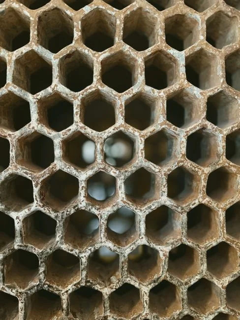
Material choice is the single biggest performance and cost lever in a refinery UF specification. The four membrane families that show up in oilfield and refinery trials behave very differently on real feedwater, and the published numbers from side-by-side comparisons are the only reliable basis for selection.
| Membrane material | Typical MWCO | Operating envelope (TMP / CFV / T) | Oil removal on refinery / produced water | Best-fit duty |
|---|---|---|---|---|
| PSF (polysulfone) | 50-100 kDa | 0.1-0.3 MPa / 1-2 m/s / 25-35 °C | Cannot bring effluent oil below 10 mg/L alone; needs NF or RO polishing | Low-cost pre-filter in a polishing train |
| PVDF (polyvinylidene fluoride) | 100 kDa | 0.30-0.35 MPa / 3.0-3.5 m/s / 35-40 °C | Oil and TSS below 1 mg/L on oilfield produced water | Reinjection spec, high-TDS refinery duty, chemical cleaning tolerance |
| PES (polyethersulfone) | 50-100 kDa | 0.1-0.3 MPa / 1-3 m/s / 25-40 °C | Greater than 96.3% TOC removal and 99.7% grease removal on refinery wastewater | Organic-rich refinery streams, high oil load |
| Composite (PSF-Al2O3 and similar) | 50-100 kDa | 0.2-0.4 MPa / 1-3 m/s / up to ~80 °C with reinforced variants | 90% oil rejection on oilfield produced water | High-temperature desalter or sour-water streams, abrasive feeds |
PSF is the lowest-cost option but, per the 2025 Hongtek comparison, cannot bring effluent oil below 10 mg/L on its own — it must be followed by nanofiltration or RO to meet discharge or reuse limits. PVDF is the workhorse for oilfield reinjection duty, where its 100 kDa rating at 0.30-0.35 MPa and 3.0-3.5 m/s cross-flow delivers oil and TSS below 1 mg/L with the strongest chemical and mechanical tolerance in the polymer family. PES is the preferred choice when organic and grease load dominates, posting the best single-pass TOC and grease removal in the published refinery data. Composite membranes are the answer when temperature, abrasion, or organic-solvent exposure exceeds the polymer-only envelope. A separate configuration — submerged hollow-fiber membrane UF (SHFMU) — was assessed in a 2026 marine spill-response life cycle study and recovered 97% of oil from recovered fluids at over 85% lower total cost than onshore transport, making it the relevant topology for offshore, FPSO, or spill-response duty (Hu et al., Marine Pollution Bulletin, 2026-05). For refinery skid builders, the practical move is to specify PVDF and PES replacement membrane elements matched to the dominant foulant in the feed.
Operating Window: TMP, Flux, Cross-Flow, and Temperature
Specifying a UF package comes down to four coupled parameters. The envelope below reflects both published refinery trials and standard hollow-fiber operating practice; treat it as the design basis you derate for feed variability.
| Parameter | Typical range (oily feedwater) | Design / derated value | Notes |
|---|---|---|---|
| TMP | 0.1-0.4 bar (0.01-0.04 MPa) | 0.2-0.3 bar | PVDF oilfield trial ran at 0.30-0.35 MPa; pushing above 0.4 bar accelerates fouling and fiber compaction |
| Flux | 40-80 LMH | 50-60 LMH | Derate for feed spikes and seasonal temperature drops that raise viscosity |
| Cross-flow velocity | 1.0-3.5 m/s | 2.5-3.0 m/s | PVDF reinjection duty used 3.0-3.5 m/s to hold oil below 1 mg/L |
| Temperature | Up to 40-45 °C (standard polymer) | 35 °C | Composite or reinforced membranes required above 45 °C |
| Single-pass recovery | 85-95% | 90% | Multi-stage (2-3 stages) keeps CFV high as retentate concentrates |
The trade-offs matter. Higher TMP raises instantaneous flux but compresses the fouling layer into a denser cake that backwash alone will not remove. Higher cross-flow velocity costs pumping energy but is the single most effective lever for keeping an oil film from blinding the membrane. Temperature is a hidden constraint — refinery desalter blowdown can arrive at 50-60 °C, and standard PVDF or PES begins to lose lifetime above 45 °C. If hot streams are in the blend, either cool with a heat exchanger upstream or move to a composite membrane rated for the higher temperature. For ancillary skid components — pressure gauges, backwash valves, instrumentation, and filter housings — the BOM is identical to any other membrane system, and selecting them from a consolidated water-treatment parts, valves, and media catalog keeps spares inventory rational across the plant.
Fouling Control, Backwash, and CIP Design
A refinery UF skid is only as good as the fouling-control strategy behind it. The standard operating cycle is air-scour combined with permeate backwash every 20-60 minutes: compressed air at 0.5-1.0 bar is introduced from below the module to agitate the fibers, followed by a reverse flow of permeate or clean filtrate at 1.5-2.5 bar for 30-90 seconds. This combination keeps the oil film from consolidating on the membrane surface between chemical cleans and is the single most important operating parameter for steady-state flux.
Pre-treatment rules are non-negotiable. Feed TSS above roughly 50 mg/L or free oil above 20 mg/L will blind hollow-fiber UF within minutes; an upstream DAF or CPI separator must polish the feed to those levels before the UF suction. The relationship between feed quality and CIP frequency is direct — a refinery feeding clean DAF effluent (TSS under 30 mg/L, oil under 15 mg/L) typically runs 4-6 weeks between CIPs, while a poorly settled feed can force weekly cleans. CIP itself is a two-step sequence: an alkaline detergent wash (NaOH 1-2% plus a surfactant at 50-60 °C) removes organic and oil foulants, followed by an acid wash (citric 1-2% or HCl 0.5-1%) to dissolve scale. Continuous antiscalant or coagulant dosing upstream of UF is unnecessary and counterproductive — that is the RO step. Over-dosing UF wastes chemical, generates sludge, and can plug the fiber bundle. For full OPEX modeling including chemical consumption, membrane replacement, and energy, the 2026 UF OPEX and membrane replacement cost breakdown is the working reference.
2026 Compliance and Reuse Targets
The same UF skid can serve three different end uses, and the compliance argument changes depending on which one the buyer is targeting. The matrix below maps membrane selection to the dominant 2026 outcomes a refinery faces.
| End use | Effluent spec (oil / TSS / SDI) | Required UF material | Upstream stage | Downstream stage |
|---|---|---|---|---|
| Surface discharge | Oil 5-10 mg/L, TSS under 30 mg/L (jurisdiction-dependent) | PES or PVDF, 50-100 kDa | DAF (PSF alone is insufficient, per Hongtek 2025) | Optional RO if TDS must drop |
| Cooling-tower or firewater reuse | Oil under 5 mg/L, TSS under 5 mg/L, SDI15 under 3 | PES or PVDF, 100 kDa | DAF + AGS (aerobic granular sludge, per 2025 refinery LCA) | RO polishing system for closed loop |
| Oilfield reinjection | Oil under 1 mg/L, TSS under 1 mg/L, particle size under 2 µm | 100 kDa PVDF at 0.30-0.35 MPa, 3.0-3.5 m/s | DAF or CPI | None typically required |
The 2025 oil-refinery process study that screened five treatment scenarios found the most sustainable path to water circularity is aerobic granular sludge (AGS) followed by UF and then a downstream RO polishing system, enabling reclaimed water to be reused as cooling-tower make-up, firefighting supply, or feed into a biological polishing unit (Hu et al., 2025). For water-stressed regions facing tightening 2026 reuse and zero-liquid-discharge drivers, that train — anchored on UF — is the defensible design basis.
Frequently Asked Questions
What pore size or MWCO should I choose for refinery wastewater?
50-100 kDa, equivalent to 0.01-0.05 µm, is the standard UF window for oily refinery feedwater. For oilfield reinjection where the spec is oil and TSS under 1 mg/L, specify 100 kDa PVDF. For organic-rich refinery streams with high grease and TOC load, prefer PES at the same 50-100 kDa range.
Can UF alone meet refinery discharge limits?
Yes, with a properly sized DAF or CPI upstream polishing the feed to TSS under 50 mg/L and free oil under 20 mg/L. Under those conditions, PES or PVDF UF routinely delivers oil under 5 mg/L and TSS under 30 mg/L, clearing typical surface-discharge permits. PSF UF alone cannot — the 2025 comparison data shows it leaves effluent oil above 10 mg/L, requiring NF or RO polishing downstream.
What is the difference between PES, PVDF, and PSF UF membranes for oil-water?
PES posts the best organic-removal numbers (greater than 96.3% TOC, 99.7% grease on refinery feedwater). PVDF has the best chemical, mechanical, and temperature tolerance, and delivers oil and TSS under 1 mg/L on oilfield produced water at 0.30-0.35 MPa and 3.0-3.5 m/s cross-flow. PSF is the lowest-cost option but cannot meet discharge spec alone and is only economic as a pre-filter in a polishing train.
Is UF enough before RO in a refinery water-reuse train?
Yes — UF is the standard RO pretreatment for refinery reuse, and the target is SDI15 under 3 to protect the RO elements. The 2025 process study on a real industrial refinery found that AGS followed by UF and RO was the most efficient and sustainable train for closing the water loop, enabling reuse as cooling make-up or firefighting supply.
How often does refinery UF need CIP cleaning?
Typically every 1-4 weeks depending on feed quality. Air-scour plus permeate backwash every 20-60 minutes keeps the oil film from consolidating between chemical cleans; the CIP itself is a two-step alkaline detergent wash followed by an acid wash for scale. For full OPEX modeling including CIP chemical, membrane replacement, and energy, the hollow-fiber PVDF ultrafiltration systems reference and the 2026 OPEX breakdown are the working documents.
Related Equipment
- upstream DAF separator — specifications, capacity range, and technical data