What the 2026 Midstream Terminal Build-Out Actually Changes for Water Management
Capacity expansion — not steady-state operation — is the event that pushes Saudi Aramco's midstream terminals past their existing water-treatment recovery ceiling. Gathering pipelines, crude stabilization trains, gas processing/sweetening units, and storage/loading racks each generate a distinct wastewater stream, and when a terminal doubles throughput, every one of those streams scales linearly while the disposal envelope does not.
Midstream operations hold 28% of the oil & gas water-treatment chemicals market, a share large enough that terminal-level equipment decisions cascade into chemical, membrane, and brine-management specifications across the value chain (USD Analytics, 2026). The segment's chemical spend is anchored by Saudi Aramco's advanced formulations for H2S scavenging, scale inhibition, and corrosion control in sour crude fields — the operating baseline any new terminal must meet or exceed (USD Analytics, 2026).
Three regulatory vectors are now squeezing the same envelope. Saudi Vision 2030 sets aggressive industrial water reuse targets, the upcoming EPA Underground Injection Control (UIC) Rule overhaul is expected to impose stricter TDS and sulfate limits on flowback and produced water reinjection, and ESG pressure is pushing operators toward closed-loop produced water reuse rather than deep-well disposal (USD Analytics, 2026). When you combine those constraints with a 2–3× capacity increase at a gathering terminal, the existing conventional RO train — already capped at 50–80% recovery — simply cannot absorb the brine load without an upgrade path.
The practical consequence: a 2026 midstream terminal expansion triggers a treatment-train review, not an automatic ZLD mandate. Most gathering, storage, and gas-processing terminals will land on high-recovery RO (90–95%) with selective brine polishing, while full ZLD remains reserved for inland sites where EOR injection demand is high and disposal-well access is constrained.
Produced Water, Desalter Effluent, and EOR Injection: The Three Streams That Drive the Decision
Three wastewater streams dominate the decision matrix at any sour-crude midstream terminal, and each carries a different TDS, H2S, and oil-in-water profile that maps to a different treatment endpoint.
Produced water from sour crude gathering typically runs 50,000–250,000 mg/L TDS, with elevated dissolved H2S, residual hydrocarbons, and scaling ions including Ba, Sr, Ca, and sulfate. This is the stream that drives the recovery ceiling problem — osmotic pressure alone can exceed 30 bar at the high end of that TDS range, which is why conventional RO tops out well before the 90% mark without pre-concentration or seed-precipitation assist. A DAF system for oil and grease removal is the standard first step; without it, free and emulsified oil will foul any downstream membrane within hours.
Desalter effluent from crude stabilization is a different animal: TDS usually sits in the 1,000–5,000 mg/L range, but oil & grease and emulsified solids are high. Desalter water is the easiest stream to recover — it is already close to RO feed quality after DAF and a multi-media filter to protect downstream RO — and it can often be blended with other site streams or sent directly to a cooling-water makeup loop.
EOR injection water specification is the binding constraint when produced water is destined for reservoir reinjection: targets are <10 mg/L suspended solids, <0.5 NTU turbidity, low sulfate (typically <100 mg/L to avoid Ba/Sr scaling in the reservoir), and <20 ppb dissolved oxygen. Those numbers cannot be reached with clarification alone — they require RO or nanofiltration, which is why any terminal feeding an EOR system effectively commits to membrane treatment.
For context, Pioneer Natural Resources targets 90% produced water reuse across its Permian assets, establishing the benchmark Saudi midstream projects are converging toward as ESG and reuse mandates tighten (USD Analytics, 2026). The table below summarizes the three streams and their typical treatment endpoint.
| Stream | Typical TDS (mg/L) | Key Contaminants | Default Endpoint | Treatment Train Anchor |
|---|---|---|---|---|
| Sour crude produced water (gathering) | 50,000–250,000 | H2S, Ba/Sr/Ca/sulfate, dispersed oil | EOR injection or brine concentrator feed | DAF → media filter → two-stage RO (± fluidized-bed crystallizer) |
| Desalter effluent (stabilization) | 1,000–5,000 | Oil & grease, emulsified solids, low H2S | Cooling-tower makeup or RO feed blend | DAF → multi-media filter → single-pass RO |
| EOR injection target (specification) | <500 (after RO) | SS <10 mg/L, <0.5 NTU, low SO4, low O2 | Reservoir injection | RO permeate + degasser + biocide dosing |
Why Conventional RO Stops at 50–80% Recovery — and What High-Recovery RO Actually Changes
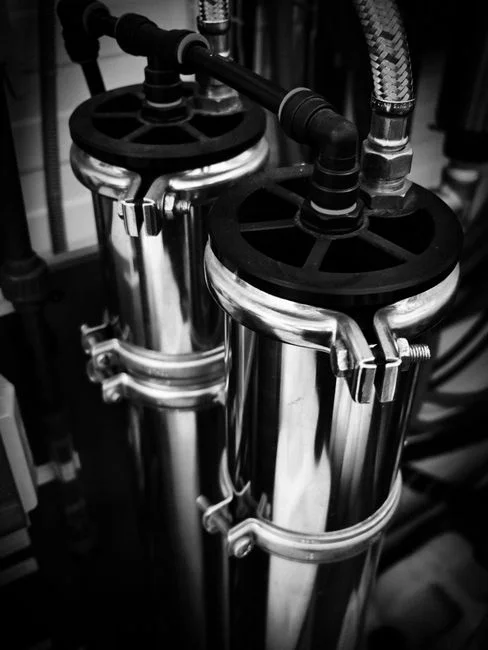
Conventional RO recovers 50–80% of feedwater and sends 20–50% out as concentrated brine — a ratio that is acceptable at a single-pass desalination plant but unacceptable at a sour-crude gathering terminal where the brine has nowhere to go (wcponline, 2026-01). The recovery ceiling is set by four engineering constraints: osmotic-pressure climb as the concentrate stream concentrates, scaling by CaCO3, BaSO4, SrSO4, and silica as their solubility products are exceeded, organic and biofouling on the membrane surface, and the specific energy per cubic meter of permeate, which rises sharply once feed pressure has to overcome osmotic pressure at the tail end of the array.
High-recovery RO in 2026 is not a single product — it is a stack of three or four techniques that together break the 80% ceiling. The first is the fluidized-bed crystallization reactor, which circulates a sidestream of RO concentrate through a vessel filled with seed particles; scale-forming salts nucleate on the seeds rather than on the membrane, the seeded crystals are periodically bled off, and the desupersaturated concentrate returns to the RO at a lower scaling index. The second is cyclic or pulsed-flow RO, which alternates production phases with brief high-velocity flushing pulses that shear off fouling layers before they mature, allowing operation closer to saturation limits with less chemical cleaning (wcponline, 2026-01).
These are not lab curiosities. A power plant in Chile operates a hybrid fluidized-bed + cyclic RO system on cooling-tower blowdown — one of the highest-scaling effluents in any industrial plant — and sustains above 93% water recovery, with the thermal stage reduced to a polishing step (wcponline, 2026-01). For a sour-crude terminal, the same combination typically delivers 90–95% overall recovery, which is the band at which the brine volume is small enough to send to a brine concentrator or class-II disposal well without overwhelming the downstream. A packaged industrial RO system with up to 95% recovery sized for 90–95% operation should be specified with anti-scalant tolerance verified against the actual produced-water ionic composition, not generic seawater data.
The MLD/RO Hybrid Path vs. Full ZLD: When Each Wins
Minimum liquid discharge (MLD) is the intermediate phase between conventional RO and full ZLD, and it is the option most midstream terminals will land on in 2026. By stacking a brine concentrator or thermal evaporator downstream of high-recovery RO, MLD shrinks the residual brine stream by 60–90% and converts most of the feed into reusable permeate (wcponline, 2026-01). In an integrated membrane-thermal hybrid, only 5–10% of the total feed reaches the evaporator or crystallizer; the rest is recovered as RO permeate and recycled (wcponline, 2026-01).
The two-stage RO configuration is the standard pre-concentration step in any MLD or ZLD train: the first stage recovers the bulk of the permeate at moderate pressure, the second stage takes the first-stage concentrate and recovers another 40–60% of it, and only the small second-stage reject is sent to the thermal stage (PMG Engineering, 2023). The two-stage RO cuts the thermal energy demand — and therefore the OPEX and carbon footprint — by an order of magnitude compared to sending raw produced water straight to an evaporator.
The decision rule is straightforward. If the terminal has access to a Class II disposal well, an EOR injection reservoir that can accept the brine, or a nearby industrial off-taker (refinery cooling water, cement kiln dust suppression), stop at MLD plus high-recovery RO — the CAPEX is a fraction of full ZLD and the OPEX is dominated by membrane replacement and antiscalant. If the terminal is inland, has no disposal pathway, or operates under a binding zero liquid discharge mandate, escalate to full ZLD with a crystallizer at the end of the train. China's oil & gas sector is the closest regulatory analog — operators there are running hybrid chemical-plus-physical produced water reuse trains under explicit ZLD policies, and that experience translates directly to inland Saudi sites (USD Analytics, 2026). For a step-by-step ZLD sizing methodology, the how to size a ZLD system step by step walkthrough applies the same mass-balance logic to a different feed.
| Configuration | Typical Overall Recovery | Thermal Energy Share | Indicative CAPEX vs. MLD Baseline | When to Choose |
|---|---|---|---|---|
| Conventional RO only | 50–80% | 0% | 0.4–0.6× | Outdated; only acceptable for low-TDS desalter effluent |
| High-recovery RO (two-stage + fluidized-bed) | 90–95% | 0% | 0.8–1.0× | Default for most midstream terminals with disposal-well or EOR access |
| MLD (high-recovery RO + brine concentrator) | 95–98% | 5–10% of feed | 1.0× (baseline) | When brine volume must be cut before transport or injection |
| Full ZLD (MLD + crystallizer) | ~99.5% | 5–10% of feed, plus crystallization | 2.0–3.0× | Inland sites, no disposal pathway, binding ZLD mandate |
Pretreatment Train That Makes High-Recovery RO Work on Sour Crude Streams
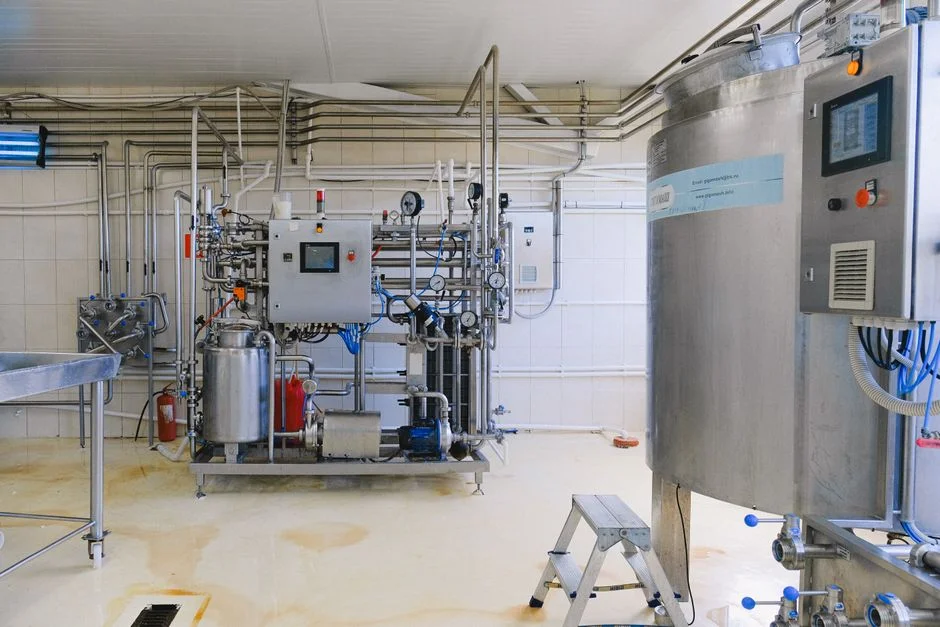
High-recovery RO is only as reliable as the pretreatment upstream. On sour crude streams, the standard sequence is: DAF or induced gas flotation for free and emulsified oil, walnut shell filtration for polishing, multi-media filtration to bring the Silt Density Index below 3, then chemical dosing for H2S scavenging, scale inhibition, and pH adjustment before the RO feed pumps. Skipping any of these stages on a sour-crude feed will collapse RO performance inside one operating quarter.
H2S removal must precede the RO membranes — RO polyamide composites are not tolerant of free H2S, and sulfate-reducing bacteria carried into the membrane array will colonize the feed spacer and destroy flux and rejection within weeks. A PLC-controlled H2S scavenger and antiscalant dosing package sized to the actual H2S loading (typically 50–500 mg/L in sour gathering systems) is the single most cost-effective reliability intervention in the train. The DAF stage is well-proven in petrochemical pretreatment and is the workhorse that keeps the media filter and RO from choking on oil; the media filter then takes the water to RO-grade SDI and protects the high-pressure pump and membrane elements from particulate fouling. Downstream monitoring and membrane cleaning chemicals round out the chemical program — and these are the fastest-growing segments in oil & gas water-treatment chemicals today, driven directly by expanded RO and NF deployment for produced water reuse (USD Analytics, 2026).
For engineers specifying the upstream membrane stage itself, the RO system for high hardness wastewater pretreatment guide walks through the antiscalant selection and recovery-target math, and the how an industrial RO system works primer covers stage and array configuration in detail.
Decision Framework: ZLD, MLD+RO, or Conventional RO by Terminal Function
The matrix below maps each midstream terminal function to its dominant wastewater stream, the recommended treatment train, the expected recovery band, and an indicative CAPEX class. The anchor figures are 90% produced water reuse (USD Analytics, 2026) and 90–95% RO recovery for high-recovery configurations (HydropureWater RO system specifications, 2026; wcponline, 2026-01).
| Terminal Function | Dominant Wastewater | Recommended Train | Expected Recovery | Indicative CAPEX Class |
|---|---|---|---|---|
| Gathering (sour crude) | Produced water, 50,000–250,000 mg/L TDS, H2S-laden | DAF → media filter → two-stage RO with fluidized-bed crystallizer → brine concentrator if EOR offtake limited | 90–95% (RO) / 95–98% (with MLD) | High (USD 8–15 per bbl/d of design flow) |
| Crude stabilization / desalter | Desalter effluent, 1,000–5,000 mg/L TDS, high O&G | DAF → multi-media filter → single-pass RO; blend with site cooling-tower makeup | 80–90% | Low to moderate |
| Gas processing / sweetening | Amine still overhead, sour water stripper bottoms, glycol-contaminated streams | O/W separation → sour water stripper → biological (if needed) → RO for reuse | 85–95% | Moderate |
| Storage and loading | Drainage, ballast, intermittent slugs | DAF → media filter → RO, or send to central terminal treatment | 85–95% | Low (often piggybacks on gathering terminal) |
| Inland EOR hub (no disposal well) | All of the above aggregated | Full ZLD: pretreatment → two-stage RO → brine concentrator → crystallizer | ~99.5% | Very high (2.0–3.0× MLD baseline) |
Full ZLD is the default only when produced water volumes exceed what EOR injection or nearby reuse off-takers can absorb. For coastal and near-coastal gathering terminals with access to a disposal well or a reservoir injection point, high-recovery MLD plus RO is the economic answer; for inland sites feeding an EOR hub, full ZLD is mandatory.
Frequently Asked Questions
Does every Saudi Aramco midstream terminal need full ZLD in 2026?
No. The 2026 expansion forces a treatment-train upgrade, not an automatic ZLD mandate. Most gathering, storage, and gas-processing terminals will meet Saudi Vision 2030 reuse targets and the upcoming EPA UIC Rule TDS/sulfate limits with high-recovery RO at 90–95% recovery plus a brine concentrator (MLD configuration). Full ZLD is reserved for inland terminals with no disposal-well access and no EOR offtake for the brine.
What recovery rate should I specify for the RO train on sour crude produced water?
Specify 90–95% overall recovery, not 75%. That band is achievable with a two-stage RO array plus a fluidized-bed crystallization reactor on the concentrate loop and cyclic/pulsed-flow operation to suppress fouling. Conventional single-pass RO at 50–80% recovery is not viable for a sour crude gathering terminal because the brine volume overwhelms downstream disposal capacity.
What pretreatment is mandatory before RO on a sour crude stream?
DAF for oil and grease, walnut shell filtration as polish, multi-media filtration to RO-grade SDI (<3), and PLC-controlled H2S scavenger plus antiscalant dosing — H2S must be removed before the RO membranes or sulfate-reducing bacteria will colonize the feed spacer and destroy performance. The full pretreatment sequence is detailed in the section above.
When is a two-stage RO worth the extra CAPEX over a single-pass system?
Whenever the brine has no cheap disposal path. Two-stage RO pre-concentrates the feed so that only 5–10% of the original volume reaches the thermal stage; this is what makes MLD or ZLD economically viable on produced water. On a coastal terminal with a Class II disposal well, single-pass high-recovery RO with a fluidized-bed reactor is often enough.
How does the Saudi regulatory backdrop compare to U.S. UIC Rule changes?
Both are converging on stricter TDS, sulfate, and reuse mandates. The upcoming EPA UIC Rule overhaul is expected to impose tighter TDS and sulfate limits on flowback and produced water reinjection (USD Analytics, 2026), which mirrors the direction Saudi Vision 2030 has set for industrial water reuse. Operators designing for the stricter of the two standards will be compliant in both jurisdictions.