What a 2026 Prefabricated WWTP Design Basis Must Contain
Prefabricated wastewater plant design criteria in 2026 are a consolidated set of engineering parameters covering influent characterization, per-stage hydraulic and organic loadings, equipment sizing, materials, instrumentation, and discharge compliance. A compliant modular WWTP typically targets effluent COD <50 mg/L (EPA) or <60 mg/L (GB 18918-2002), achieves 85–95% COD and 90–98% BOD removal, and occupies 50–70% less footprint than a site-built plant at 3–6 month deployment (HydropureWater field data, 2026).
A design basis is the auditable set of parameters a modular supplier is contracted against — it is the document a process engineer pastes into a Design Basis Memorandum and the document an EPC firm references on a P&ID. In 2026, the basis must explicitly align with EPA 40 CFR Parts 122 and 503, China GB 18918-2002, EU Directive 91/271/EEC, and WHO reuse guidelines where applicable. Headline compliance targets should be stated up front: COD <50 mg/L for EPA industrial discharge, COD <60 mg/L for GB 18918-2002, BOD <10 mg/L for reuse class, turbidity <1 NTU for MBR polish. The remainder of this article is organized as six parameter blocks — influent characterization, hydraulic/preliminary, biological, tertiary/sludge, containerized layout/materials, and I&C/commissioning — each with the loadings, retention times, and code references an engineer needs to freeze a 2026 specification.
| Parameter Block | Key 2026 Target | Primary Code Reference |
|---|---|---|
| Effluent COD | <50 mg/L (EPA) / <60 mg/L (GB 18918-2002) | EPA 40 CFR Part 122; GB 18918-2002 |
| Effluent BOD | <10 mg/L (reuse) / <30 mg/L (discharge) | EPA 40 CFR Part 133; WHO reuse |
| TSS | <20 mg/L (MBR polish) | EPA 40 CFR Part 133 |
| Turbidity | <1 NTU (MBR reuse) | WHO reuse guidelines |
| Footprint | 50–70% less than site-built | Project specification |
| Deployment | 3–6 months order-to-commissioning | Project specification |
Influent Characterization Criteria
Wrong influent data is the single most common cause of undersized prefab plants, and the design basis must lock characterization before module selection. Required parameters are COD, BOD₅, TSS, FOG, total nitrogen, total phosphorus, pH, temperature, peak diurnal factor, and industry-specific contaminants (heavy metals, salts, solvents). Typical industrial influent bands the criteria must accommodate in 2026: food processing COD 3,000–5,000 mg/L, dairy BOD 1,500–2,500 mg/L, semiconductor rinse COD 100–300 mg/L, pulp and paper TSS >500 mg/L (HydropureWater field data, 2026). Equalization must buffer flows of 20–300 m³/h with COD up to 2,000 mg/L and dampen peak factors of 1.5–2.5× average. Sampling protocol: 24-h composite plus 3-h grab, minimum 5 consecutive working days, before design freeze. A GX series rotary mechanical bar screen protects downstream membranes and DAF nozzles from debris that would otherwise force emergency shutdowns.
| Industry | COD (mg/L) | BOD (mg/L) | TSS (mg/L) | FOG (mg/L) |
|---|---|---|---|---|
| Food processing | 3,000–5,000 | 1,500–2,500 | 500–1,500 | 200–800 |
| Dairy | 2,000–4,000 | 1,500–2,500 | 300–800 | 100–400 |
| Semiconductor rinse | 100–300 | 50–150 | <50 | <20 |
| Pulp & paper | 1,500–4,000 | 700–2,000 | 500–2,500 | <100 |
| Landfill leachate | 5,000–15,000 | 3,000–8,000 | 200–600 | <50 |
Hydraulic and Preliminary-Treatment Criteria
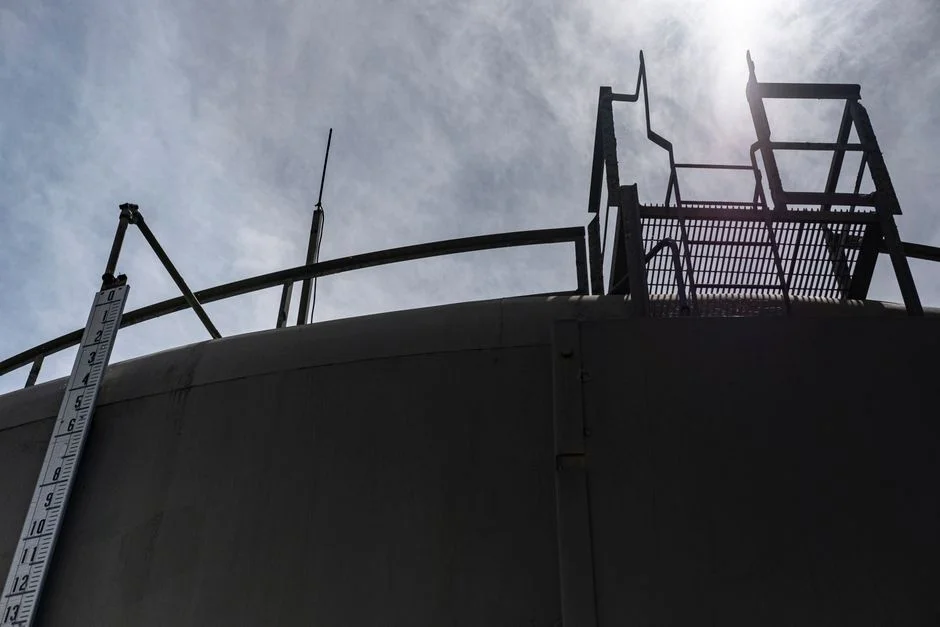
Preliminary treatment sets the upstream margin the biological skid will live with for the next 15 years. Screen aperture must be specified at ≤1 mm opening for fine screening, which protects downstream UF/RO membranes and DAF nozzles from ragging and grit carry-over. Equalization tank HRT sits at 6–12 h at average flow with 25% freeboard for surge. DAF criteria: saturation pressure 0.5–1.5 bar, micro-bubble diameter 30–50 μm, surface loading 5–15 m/h, target 92–97% TSS removal and 60–80% FOG removal (HydropureWater field data, 2026). A peak-flow bypass with automatic diversion to an emergency holding tank sized for 2× peak hourly flow is non-negotiable — it is the difference between a controlled shutdown and an environmental incident. Energy for the DAF stage is budgeted at 0.3–0.5 kWh/m³, with micro-bubble generation accounting for ~60% of that load. Designers should also size the equalization tank to maintain influent COD variability below ±15% of the 24-h composite average before the DAF feed pumps.
| Parameter | Criterion | Engineering Basis |
|---|---|---|
| Fine screen aperture | ≤1 mm | Membrane/DAF protection |
| Equalization HRT | 6–12 h (avg flow) | Peak dampening |
| Equalization freeboard | ≥25% | Surge margin |
| DAF saturation pressure | 0.5–1.5 bar | Micro-bubble generation |
| DAF micro-bubble diameter | 30–50 μm | Buoyant attachment |
| DAF surface loading | 5–15 m/h | Hydraulic capacity |
| DAF TSS removal | 92–97% | Influent ≤5,000 mg/L |
| DAF FOG removal | 60–80% | Influent 100–300 mg/L |
| Emergency holding | 2× peak hourly flow | Bypass sizing |
A dissolved air flotation system is the standard primary-removal block referenced in this design basis.
Biological-Treatment Design Criteria (MBR / A/O / SBR)
The biological skid is where the design basis earns its keep. MBR criteria: MLSS 8,000–12,000 mg/L, MLVSS 5,000–8,000 mg/L, HRT 6–10 h at average flow, SRT 20–30 d, F/M 0.05–0.15 kg BOD/kg MLVSS·d. A/O (anoxic/aerobic) criteria: anoxic HRT 2–4 h, aerobic HRT 8–10 h, internal recycle 200–400%, COD removal 85–95%, BOD 90–98% (HydropureWater field data, 2026). Aeration: dissolved-oxygen setpoint 1.5–2.5 mg/L in the aerobic zone, 0.2–0.5 mg/L in the anoxic zone; SOTE ≥30% for fine-bubble diffusers. MBR membrane criteria: PVDF flat-sheet, 0.1 μm pore, flux 12–20 L/m²·h, transmembrane pressure ≤30 kPa, integrated aeration box for scouring. Energy budget for the biological stage: 0.6–1.2 kWh/m³ for MBR, 0.3–0.5 kWh/m³ for DAF upstream. The choice between an integrated MBR membrane bioreactor system and a conventional A/O train turns on three numbers: target effluent BOD (<10 mg/L pushes MBR), influent COD variability (MBR tolerates wider swings), and footprint (MBR is typically 30–50% smaller).
For high-strength streams, an anaerobic MBR front-end can lift the upper COD bound to roughly 15,000 mg/L, with the downstream aerobic stage polishing to discharge. Designers should also specify wasting rates to maintain SRT 20–30 d and verify that the membrane aeration box receives a dedicated blower sized at 0.3–0.4 m³ air per m² membrane area per minute. The DF series PVDF flat-sheet MBR membrane module is the typical 2026 spec for industrial reuse applications.
| Parameter | MBR | A/O (anoxic/aerobic) |
|---|---|---|
| HRT (avg flow) | 6–10 h | 10–14 h (2–4 anoxic + 8–10 aerobic) |
| SRT | 20–30 d | 15–25 d |
| MLSS | 8,000–12,000 mg/L | 3,000–5,000 mg/L |
| MLVSS | 5,000–8,000 mg/L | 2,000–3,500 mg/L |
| F/M | 0.05–0.15 kg BOD/kg MLVSS·d | 0.10–0.25 |
| DO setpoint (aerobic) | 1.5–2.5 mg/L | 1.5–2.5 mg/L |
| DO setpoint (anoxic) | 0.2–0.5 mg/L | 0.2–0.5 mg/L |
| COD removal | 85–95% | 85–95% |
| BOD removal | 90–98% | 90–98% |
| Energy | 0.6–1.2 kWh/m³ | 0.4–0.8 kWh/m³ |
Tertiary, Disinfection, and Sludge-Handling Criteria
Tertiary polishing closes the reuse loop. Multi-media filter: TSS removal ≥95%, bed depth 1.0–1.2 m, backwash at ΔP 0.7 bar. RO permeate (when reuse requires desalination) achieves salt rejection ≥99%. Disinfection: chlorine dioxide or ozone achieving 99.9% microbial kill; ClO₂ residual 0.1–0.5 mg/L after 30-min contact time; biosolids must comply with EPA 40 CFR Part 503 Class A. Sludge dewatering: plate-and-frame press to 25–35% dry solids, reducing sludge volume 40–60% versus thickened sludge. Sludge storage: covered hopper, ≥7 days holding capacity at peak production, supernatant returned to headworks. Designers should also specify supernatant recycle piping back to the equalization tank and confirm that the dewatering building has negative-pressure ventilation to control aerosolized pathogens during cake discharge.
| Stage | Target | Key Parameter |
|---|---|---|
| Multi-media filter | ≥95% TSS removal | Backwash ΔP 0.7 bar; bed 1.0–1.2 m |
| RO permeate | ≥99% salt rejection | For reuse requiring low TDS |
| Disinfection (ClO₂ / O₃) | 99.9% microbial kill | ClO₂ residual 0.1–0.5 mg/L, 30-min CT |
| Biosolids | EPA 40 CFR Part 503 Class A | Pathogen reduction |
| Sludge dewatering | 25–35% dry solids | 40–60% volume reduction |
| Sludge storage | ≥7 d holding at peak | Covered hopper; supernatant recycle |
Reference equipment: multi-media filter for tertiary polish, chlorine dioxide generator for disinfection, and plate-and-frame filter press for sludge dewatering. For higher-strength reuse trains, see Reverse Osmosis for COD Removal: 2026 Engineering Specs for RO sizing specifics.
Containerized vs Skid-Mounted Layout, Materials, and Footprint Criteria
The layout decision is as much procurement as process. Containerized criteria: 20-ft or 40-ft ISO container, walk-in access, HVAC to keep internal temperature 5–40 °C, lifting lugs, fork pockets; suitable for temporary/remote sites (mining camps, construction, emergency response). Skid-mounted criteria: hot-dip galvanized or epoxy-coated carbon steel frame, 1–80 m³/h flow per skid, designed for permanent factory installation. Materials of construction: SS304 for general wetted parts, SS316L or FRP for chloride/chromium service; lining 1.5–3 mm PVC, PE, or rubber for aggressive streams (HydropureWater field data, 2026). Footprint target: ≤0.4 m² per m³/day (e.g., 200 m² for 500 m³/day); 50–70% smaller than site-built equivalents. A common engineering pitfall is specifying HVAC for ambient-only operation in cold climates — internal temperatures below 5 °C push biological activity below acceptable F/M, so heaters or insulation must be explicit in the basis. Reference layouts: WSZ underground integrated sewage treatment equipment for space-constrained urban sites, and the PLC-controlled chemical dosing skid for coagulant/pH adjustment across the train.
Instrumentation, Control, and Commissioning Acceptance Criteria
I&C is where 95% of prefab plants pass first-time compliance, and where 5% of site-built plants repeat the same six-month punch list. Instrumentation minimum: influent pH, flow, conductivity; basin DO, MLSS, TSS; effluent pH, COD (online), turbidity, residual disinfectant; chemical-dosing flow with ±1% accuracy. Control: PLC with HMI/SCADA, remote telemetry, automatic chemical-dosing skids with PLC-controlled injection of coagulant, flocculant, and pH adjuster. Factory acceptance test (FAT): performance test with clean water at design flow, leak test 1.5× working pressure for 2 h, control-loop simulation. Site acceptance: 72-h performance trial at design flow meeting effluent targets (COD <50 mg/L, TSS <20 mg/L, turbidity <1 NTU for MBR) — the basis for the 95% first-time compliance rate (HydropureWater field data, 2026).
| Test | Duration / Condition | Pass Criterion |
|---|---|---|
| FAT — clean water performance | Design flow | All flow/P&ID loops verified |
| FAT — leak test | 1.5× working pressure, 2 h | No pressure decay |
| FAT — control-loop simulation | All I&C loops | PLC/HMI response <2 s |
| SAT — 72-h performance trial | Design flow, real influent | COD <50 mg/L; TSS <20 mg/L; turbidity <1 NTU |
| Online COD analyzer calibration | Pre-SAT | ±5% vs laboratory COD |
| First-time compliance rate | Project handover | 95% (HydropureWater field data, 2026) |
Modular Sizing Logic and 2026 Cost Benchmarks
Sizing logic the EPC can paste into a basis-of-design: design flow = average flow × peak factor (1.5–2.5) × 1.2 future-growth factor. Worked example: 100 m³/h average → 180–300 m³/h peak design. CapEx criterion: $500–$2,000/m³/day for prefab versus $800–$3,000/m³/day site-built, a 20–30% saving. OPEX criterion: energy 0.3–1.2 kWh/m³ (30–40% lower than site-built), chemical cost ~20% lower via automated dosing. Lead time criterion: 3–6 months order-to-commissioning versus 12–24 months site-built; containerized emergency units operational in ~4 weeks. For specialized sizing cases, see Photoresist Wastewater Treatment by MBR: 2026 Engineering Specs and How to Size MBR for Bleach E-Stage Effluent: 2026 Engineering Specs.
| Criterion | Prefab / Modular | Site-Built |
|---|---|---|
| CapEx | $500–$2,000/m³/day | $800–$3,000/m³/day |
| OPEX energy | 0.3–1.2 kWh/m³ | 1.5–2.5 kWh/m³ |
| Chemical cost | ~20% lower (automated dosing) | Baseline |
| Lead time | 3–6 months (4 weeks emergency) | 12–24 months |
| Footprint (500 m³/d) | ~200 m² | ~600 m² |
| First-time compliance | ~95% | ~70% |
Frequently Asked Questions
What are the minimum design criteria for a prefabricated WWTP in 2026?
The minimum design criteria are the six parameter blocks covered above: (1) influent characterization with 24-h composite sampling over 5 working days, (2) hydraulic/preliminary treatment with ≤1 mm screening and 6–12 h equalization HRT, (3) biological treatment with MLSS 8,000–12,000 mg/L and F/M 0.05–0.15 for MBR, (4) tertiary and disinfection meeting COD <50 mg/L and turbidity <1 NTU, (5) containerized or skid-mounted layout with HVAC and SS304/SS316L materials, and (6) I&C and commissioning with FAT and a 72-h SAT at design flow.
How is hydraulic loading calculated for a modular plant?
Design flow = average flow × peak factor (1.5–2.5) × 1.2 future-growth factor. A 100 m³/h average feed becomes a 180–300 m³/h peak design. The 20% growth multiplier is standard practice to absorb the first five years of plant expansion without re-engineering the biological skid.
What effluent parameters must a prefab WWTP meet for industrial discharge?
For EPA industrial discharge: COD <50 mg/L, BOD <30 mg/L, TSS <30 mg/L. For GB 18918-2002: COD <60 mg/L, BOD <20 mg/L, TSS <20 mg/L. For reuse class (cooling tower makeup, irrigation): BOD <10 mg/L, turbidity <1 NTU, and RO permeate if TDS reduction is required.
How much smaller is a prefab plant than a site-built equivalent?
A 2026 modular plant occupies 50–70% less footprint than a site-built plant of equivalent capacity. Concrete example: a 500 m³/day prefab plant occupies ~200 m², versus ~600 m² for a site-built equivalent of the same hydraulic capacity. The reduction comes from eliminating separate clarifiers, integrating MBR cassettes, and tightening pipe runs inside ISO containers.
Can a modular WWTP handle high-strength industrial wastewater (COD >1,000 mg/L)?
Yes. A/O trains with MBR polish handle COD up to ~5,000 mg/L with proper pre-treatment (screening, equalization, DAF for FOG). For COD above ~10,000 mg/L — landfill leachate, concentrated food processing, distillery stillage — an anaerobic MBR front-end is specified, with the downstream aerobic stage polishing to discharge. The DAF, biological, and MBR modules are sized independently so each stage operates within its own loading envelope.