Why Scrubber Blowdown Is the Hardest MBR Feed in a Smelter
Smelter scrubber blowdown pretreatment before MBR requires quench cooling to ≤38 °C, two-stage metal precipitation, and filtration to ≤5 mg/L TSS. Typical blowdown runs 5–40 m³/h at 45–65 °C with chloride 2,000–20,000 mg/L. Without that train, PVDF membranes foul or delaminate within weeks.
The feed is clarifier overflow from wet FGD absorbers, acidic mist-eliminator wash, and gas-cooling liquor, with peaks 3–5× higher during batch tapping (HydropureWater field data, 2026). According to US EPA Nonferrous Metals Manufacturing Effluent Guidelines, wet-scrubber air-pollution-control streams are a core wastewater source at primary and secondary smelters (40 CFR Part 421). On paper an MBR is the cheapest path to low-TSS clarifier effluent. In practice four datasheet numbers kill membranes: temperature 45–65 °C, TDS 5,000–45,000 mg/L, chloride 2,000–20,000 mg/L, and TSS 200–4,000 mg/L from gypsum fines and fly-ash carryover. Mercury, arsenic, selenium, lead, cadmium, and zinc sit in the 0.1–50 mg/L range, with pH swinging between 1 and 5 across a shift.
Feed that stream to a 0.1 µm PVDF module and three failures arrive together. Temperature exceeds the 38–40 °C PVDF service ceiling, so the polymer softens and the membrane delaminates within weeks. Gypsum crystals (CaSO₄·2H₂O) and fly-ash particles below 50 µm blind the surface in hours, driving transmembrane pressure past 0.4 bar. Chloride above 8,000–10,000 mg/L suppresses nitrifiers, while dissolved heavy metals accumulate in the biomass, kill it, and re-dissolve when pH drifts. An MBR Membrane Bioreactor Wastewater Treatment System can finish the job, but only after a dedicated pretreatment train pulls each parameter back inside the membrane envelope.
Contaminant-to-MBR-Feed Specification
The contaminant-to-MBR-feed specification below is the sheet procurement pins to the control-room wall. It maps every parameter on a typical smelter blowdown sheet to the maximum a PVDF flat-sheet MBR can tolerate, and the reason that limit exists. The MBR feed targets assume a 0.1 µm submerged module operated at 12–18 L/m²·h flux, such as the DF series PVDF flat sheet MBR modules, which draw 10–20× less energy than cross-flow designs at this solids loading.
| Parameter | Typical Blowdown Range | MBR Feed Target | Reason for Limit |
|---|---|---|---|
| Temperature | 45–65 °C | ≤38 °C | PVDF service ceiling (manufacturer data, DF series) |
| TSS | 200–4,000 mg/L | ≤5 mg/L | 0.1 µm membrane blinding by gypsum/fly ash |
| TDS | 5,000–45,000 mg/L | ≤30,000 mg/L preferred | Osmotic stress on biomass, foam, salt crusting |
| Chloride (Cl⁻) | 2,000–20,000 mg/L | <8,000 mg/L for nitrification | Nitrifier inhibition; corrosion of ancillary steel |
| FOG | 10–80 mg/L | <10 mg/L | Membrane pore blockage and biofilm gas-locking |
| Mercury (Hg) | 0.1–10 mg/L | ≤0.1 mg/L | Biomass poisoning; EU BAT-AEL compliance |
| Arsenic (As) | 0.5–30 mg/L | ≤0.5 mg/L | Discharge permit and biomass uptake |
| Selenium (Se) | 0.2–20 mg/L | ≤0.5 mg/L | Selenate passes biological stage; needs precipitation |
| pH | 1–5 | 6.5–7.5 | Biomass comfort and metal hydroxide stability |
If any left-column parameter cannot reach the target by pretreatment, re-engineer the train. The usual fix is a slipstream RO before the MBR, as covered in Stage 4 below.
Pretreatment Stage 1 — Quench Cooling and Equalization
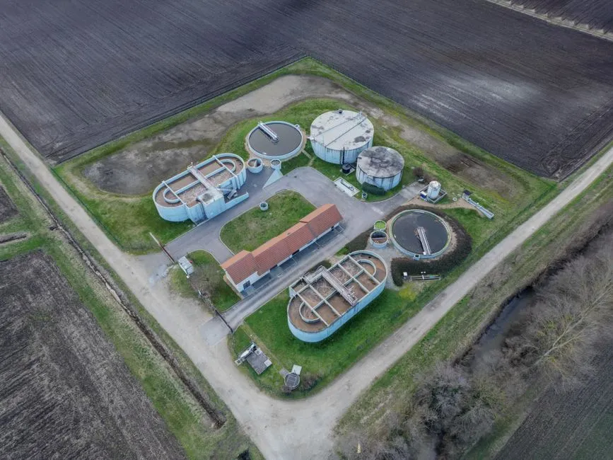
Quench cooling and equalization drop blowdown from 50–60 °C to ≤38 °C and flatten the hydraulic and chemical spikes that ride in from batch converter operations. A forced-draft or induced-draft cooling tower sized for 1.3× the design flow with a 20–25 °C approach to wet-bulb is the workhorse for most smelters. Plate heat exchangers (PHEs) fit when the plant wants to recover heat for low-pressure wash water or when makeup water is restricted. Titanium plates are mandatory above 8,000 mg/L Cl⁻, since 316L pitting starts within months in that range.
Downstream of cooling, an equalization basin sized for 12–24 h HRT dampens the 3–5× flow swings, the pH excursions (raw 1–5, equalized 4–6), and the temperature spikes that follow matte-tap events. The EQ tank is typically aerated concrete or FRP with two submersible mixers on a duty/standby basis. Aeration also strips a portion of dissolved SO₂ and CO₂, raising pH by 0.5–1.0 units for free. Material selection matters: FRP or rubber-lined carbon steel handles chloride service; 316L is acceptable only on low-chloride copper-smelter blowdown below 4,000 mg/L Cl⁻. From the EQ tank the stream is pumped at a steady rate to the chemistry stage, which keeps coagulant dose from chasing a moving target.
Pretreatment Stage 2 — pH Adjustment and Heavy-Metal Precipitation
Heavy-metal precipitation for smelter scrubber blowdown needs two pH windows because no single setpoint removes all six regulated metals reliably. Stage 2A is a hydroxide raise to pH 8.5–9.0 with lime (Ca(OH)₂) or NaOH, which drops arsenic, lead, cadmium, zinc, and copper to sub-mg/L concentrations as their hydroxides. Lime is cheaper per kg but adds calcium sulfate scale downstream. NaOH is cleaner and easier to control, and is fed via a PLC-controlled automatic chemical dosing system with a redundant pH probe in a slipstream.
Stage 2B is where smelter blowdown differs from generic metal-finishing wastewater. Mercury and selenium do not precipitate cleanly with hydroxide alone, and above about 8,000 mg/L Cl⁻ mercury stays in solution as HgCl₄²⁻ regardless of pH. The fix is a sulfide or strong-reductant stage at pH 9.5–10.5: TMT-15 (2,4,6-trimercaptotriazine) at 5–15 mg/L per mg Hg, or Na₂S at 1.0–1.5× stoichiometric dose, converts mercury to a stable sulfide sludge. Selenium as selenate (SeO₄²⁻) requires prior reduction to selenite with FeCl₃ at pH 7–8, then co-precipitation with the metal hydroxides. Reaction time is 20–30 min per stage with 50–100 rpm flash mixing, polymer dose 0.5–2 mg/L for flocculation, and sludge production 3–8 kg/m³ of blowdown — typically sent to a dedicated heavy-metal sludge thickener, not the gypsum pile. Above 15,000 mg/L Cl⁻, sulfide dosing becomes mandatory rather than optional because chloro-complex equilibria keep mercury soluble below pH 10.5.
Pretreatment Stage 3 — Clarification and Multi-Media Filtration

Clarification and multi-media filtration must strip precipitates before membranes see them. A lamella clarifier (high-efficiency sedimentation tank) operating at 20–40 m³/m²·h surface loading captures the bulk of the metal-hydroxide and gypsum sludge, with sludge recirculation maintaining a stable blanket at 1–3% solids. Overflow turbidity is typically 20–50 NTU, which is not enough for a 0.1 µm membrane — gypsum crystals below 20 µm slip through the lamella packs and will foul the module within a shift. The lamella clarifier design used here should be specified with 60° plate spacing and a 50 mm mud-thickener cone to handle the high specific gravity of gypsum-laden sludge.
Polishing to the MBR's ≤5 mg/L TSS target is done in a down-flow multi-media filter with anthracite (0.8–1.2 mm, 0.5 m), silica sand (0.45–0.55 mm, 0.3 m), and garnet (0.2–0.3 mm, 0.1 m) at 10–15 m/h filtration velocity. The multi-media filter is on a 24 h backwash cycle using filtered water plus air-scour, and a periodic soak with 1% HCl to dissolve accumulated calcium sulfate scale. With this train online, the MBR feed should read under 5 mg/L TSS and below 2 NTU. Verify online with a laser-turbidity meter rather than grab samples. Gypsum precipitation in the sample line will mislead the operator.
Pretreatment Stage 4 — Optional Conditioning for High-TDS Streams
Optional high-TDS conditioning applies to zinc roaster smelters and copper smelters drawing scrubber water from seawater. When TDS exceeds 30,000 mg/L or chloride exceeds 15,000 mg/L, osmotic pressure across the MBR membrane drops flux below 8 L/m²·h, halophilic biomass activity falls by half, and conventional nitrification effectively stops. Field experience confirms that a halophilic seed needs 4–6 weeks of acclimation and 50% larger aeration tanks to deliver the same BOD removal. Most plants we size for seawater-scrubbed copper lines run at the lower end of the flux band once salinity climbs past 30,000 mg/L TDS.
The cleaner engineering answer is a split-stream: send the clarified, metal-precipitated effluent to a brackish-water RO system at 70–80% recovery, and feed only the RO permeate (TDS typically 200–500 mg/L) to the MBR. The RO concentrate (TDS 80,000–120,000 mg/L) goes to the smelter's existing evaporation pond or crystallizer. This is a higher-capex route but it converts a biological problem into a membrane one, which is easier to operate and far easier to permit. For smelters that already have an RO train for boiler feed, this is rarely a new line item — it is a tie-in.
Smelter Scrubber Blowdown Pretreatment Before MBR
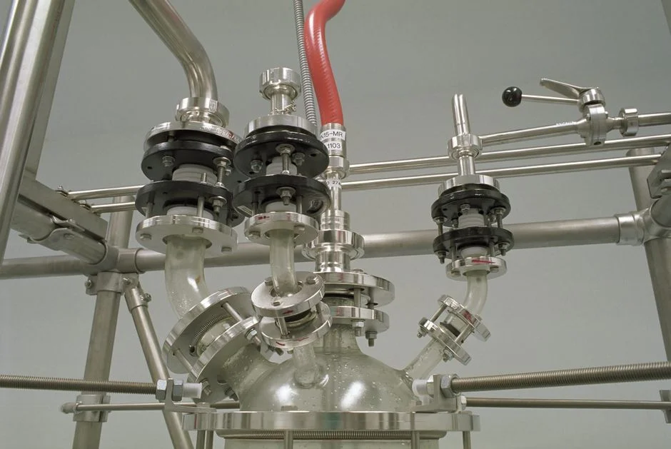
Smelter scrubber blowdown pretreatment before MBR sets the sizing envelope once the parameter table is met. Expect mixed-liquor suspended solids (MLSS) of 8,000–12,000 mg/L, HRT of 6–10 h, and sustainable flux of 12–18 L/m²·h for a submerged DF-series module operated at −0.1 to −0.3 bar suction. Operating at 15 L/m²·h with intermittent backflush is a better long-run choice than chasing 22 L/m²·h and buying a chemical-cleaning problem. Plan for relaxation-mode backflush every 8–12 min (45 sec on, 8 min off). Add in-line chemical cleaning with 500–1,000 mg/L NaOCl every 7–14 days. Scrubber bleed streams always carry trace mercury, arsenic, and selenium that stress the biomass even after precipitation. Sizing logic is similar in principle to sizing an MBR for e-coat UF reject, but the salinity ceiling is the controlling constraint here rather than the organic load.
Selection Checklist and Cost Drivers
Selection checklist items for a smelter blowdown-to-MBR train are concrete, not brochure claims. Confirm wet-bulb approach and cooling duty for peak tapping temperatures of 45–65 °C. Size equalization for 12–24 h HRT at 3–5× hydraulic peaks. Choose hydroxide then sulfide/TMT chemistry for Hg and Se when Cl⁻ exceeds about 8,000 mg/L. Spec lamella plus multi-media filtration to ≤5 mg/L TSS and <2 NTU. Trigger sidestream RO when TDS exceeds 30,000 mg/L or Cl⁻ exceeds 15,000 mg/L. Hold MBR flux at 12–18 L/m²·h with NaOCl CIP every 7–14 days. Budget sludge handling for 3–8 kg/m³ of blowdown as a dedicated hazardous stream.
Main cost drivers are titanium heat-exchange surface above 8,000 mg/L Cl⁻, sulfide or TMT reagent consumption at high mercury, gypsum-laden sludge dewatering, and the optional RO/crystallizer train on seawater scrubbers. Membrane replacement risk tracks temperature and TSS excursions more than COD load on these feeds.
Who This Is For / Who Should Look Elsewhere / Next Step
Who this is for: process engineers and EPC teams specifying wet-scrubber blowdown trains for copper, zinc, lead, or secondary nonferrous smelters. They need stable MBR permeate for reuse or discharge. Who should look elsewhere: plants with only dry scrubber ash and no liquid blowdown, or gypsum stack water without dissolved Hg/Se. Next step: send a recent blowdown datasheet (temperature, Cl⁻, TDS, TSS, Hg, As, Se, pH, flow peaks) for a pretreatment-plus-MBR block flow via our request a quote form.
Frequently Asked Questions
What is the maximum temperature scrubber blowdown can be at the MBR feed?
≤38 °C for a standard PVDF flat-sheet module; 40 °C is the absolute short-term ceiling and any sustained operation above 35 °C shortens membrane life noticeably (DF series manufacturer data, 2026). Most plants we size for keep feed at 32–36 °C to leave headroom when wet-bulb rises in summer.
What chloride concentration forces a split-stream RO design instead of direct MBR feed?
Cl⁻ above 15,000 mg/L — or TDS above 30,000 mg/L — should trigger a sidestream RO with permeate fed to the MBR. Nitrification and sustainable flux both collapse in standard biomass at that salinity. Seawater-scrubbed copper lines hit this threshold first.
Why can't mercury be removed by hydroxide precipitation alone in smelter blowdown?
Above ~8,000 mg/L Cl⁻, mercury forms soluble chloro-complexes (HgCl₄²⁻) that stay in solution up to pH 10.5; a sulfide or TMT-15 stage at pH 9.5–10.5 is required to drop Hg to ≤0.1 mg/L. Hydroxide alone is enough only on low-chloride copper blowdown.
What TSS target protects a 0.1 µm submerged MBR module from blinding?
≤5 mg/L TSS and below 2 NTU at the MBR feed protect a 0.1 µm module. Achieve that with a lamella clarifier followed by a multi-media anthracite-sand-garnet filter. Gypsum carryover is the most common cause of premature fouling when this target is missed.
How should MBR flux be set after blowdown pretreatment?
Sustainable flux of 12–18 L/m²·h at −0.1 to −0.3 bar suction is the design band for submerged DF-series PVDF modules on pretreated scrubber blowdown. Holding near 15 L/m²·h with 8–12 min relaxation cycles usually beats chasing 22 L/m²·h and frequent chemical cleans.