Why Copper Concentrator Water Fails Straight to DAF
Pretreatment is non-optional for copper concentrator water. Sending raw thickener overflow or tailings water directly to a dissolved air flotation unit triggers three documented failure modes that drive both compliance risk and operating cost. First, froth collapse: residual xanthate (1–20 mg/L) and dithiophosphate (0.5–10 mg/L) collectors poison the air–water interface and rupture the micro-bubbles the DAF relies on for particle attachment, producing a thin, watery float that carries little solids. Second, copper re-flotation: when pH drifts above 8.5, the precipitated CuS converts back to soluble cuprous/ferrocyanide complexes, which the rising bubbles then carry into the float layer instead of removing them — so the DAF effectively re-concentrates copper on the surface. Third, TSS capture falls below 60% because ultrafine gangue particles under 10 μm pass the bubble attachment window entirely; they need coag–floc conditioning first to grow into a settleable/attachable floc.
DAF was originally optimized for low-TDS industrial matrices. The Durban University of Technology work on continuous DAF for industrial mineral oil–water separation is the operating philosophy the engineer should demand of the DAF vendor, but copper mill water is a much heavier, reagent-laden stream by comparison. The cost of skipping pretreatment is concrete: DAF effluent fails typical copper discharge limits (dissolved Cu <0.5 mg/L) and the unit generates 2–3× its normal sludge volume because untreated colloids blind the float and recycle back through the saturator.
Copper Concentrator Water Characterization: What You're Treating
Before you specify a pretreatment train, you need a realistic influent envelope. The table below summarizes typical copper concentrator thickener-overflow and tailings-water parameters drawn from process convention rather than single-source lab data — use it to compare against your plant's daily composites and select pretreatment intensity accordingly.
| Parameter | Typical Range | Source of Variability |
|---|---|---|
| Total suspended solids (TSS) | 200–3,000 mg/L | Flotation tailings fines, ore grade shifts |
| pH | 7–11 | Lime/NaOH circuits, residual acid from upstream leach |
| Residual sulfide (S²⁻) | 0.5–15 mg/L | NaHS dosing, pyrrhotite oxidation |
| Dissolved copper (Cu²⁺) | 0.5–50 mg/L | Ore mineralogy, recycle water chemistry |
| Residual xanthate (KAX/SIBX) | 1–20 mg/L | Flotation circuit losses, scavenger addition |
| Dithiophosphate (DTP) | 0.5–10 mg/L | Sulfide mineral collectors |
| Frother (MIBC) | 0.2–2 mg/L | Frother overdosing in flotation |
| Temperature | 15–35 °C | Climate, mill discharge temperature |
| Total dissolved solids (TDS) | 800–4,000 mg/L | Recycle water, process water make-up |
The collectors and frothers are the compounds that poison DAF micro-bubbles if they are not stripped, oxidized, or diluted first. The 800–4,000 mg/L TDS window is also important: higher TDS compresses the double layer on colloids and increases coagulant demand, while temperature shifts of 15–35 °C change reaction kinetics enough that the dose setpoint you commission in winter will not hold in summer.
Pretreatment Stage 1: Screening and Grit Removal
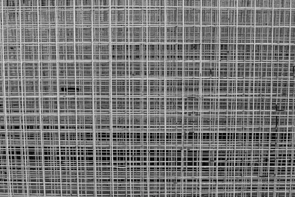
The first unit operation is always headworks protection. Specify a rotary mechanical bar screen with 3–6 mm openings on the thickener overflow stream — this lifts out wood chips, rags, and coarse ore fragments that would otherwise wrap on DAF recycle-pump impellers and starve the saturator of pressurized water. For a 24/7 concentrator, a self-cleaning GX series rotary bar screen is preferred over manual baskets because rags accumulate fast enough that a missed basket cleanout takes a DAF cell down within hours.
Hydraulic loading for fine screening on this service typically runs 30–60 m³/h per meter of screen width at the 200–3,000 mg/L TSS envelope above. Below 30 m³/h/m the screen loses self-cleaning velocity and solids blind the bars; above 60 m³/h/m the head loss climbs and you start pushing screenings through the apertures. Coarse grit greater than 6 mm is removed here so the downstream pH-adjustment basin and DAF internals do not see tramp material.
Pretreatment Stage 2: pH Adjustment and Sulfide Precipitation
The second stage is where the chemistry does the heavy lifting. The reaction is straightforward:
Cu²⁺ + S²⁻ → CuS↓ (s)
at pH 6.5–7.5, with NaHS or Na₂S dosed at 1.2–1.5× the stoichiometric requirement of the residual dissolved copper. The 1.2–1.5× factor is a deliberate excess to keep residual S²⁻ low and drive the reaction to completion, but it must not be so high that free sulfide carries over into the DAF and re-dissolves precipitated CuS. The pH window is non-negotiable: below 6.0, CuS becomes unstable and re-dissolves; above 8.0, the same reaction reverses and the rising bubbles lift copper into the float instead of dropping it out.
After sulfide precipitation, reconfirm pH at 6.5–7.5 before sending the water to coagulation. Use sulfuric acid (H₂SO₄) for pH trim — not HCl — because chloride ions attack 904L stainless steel in DAF saturators and shorten vessel life by a factor of 2–3. If the upstream leach circuit ran acidic and the water arrives below pH 6, lift with lime (Ca(OH)₂) or NaOH before sulfide addition. The dissolved-copper recovery angle is what makes this step worth the chemistry: sulfide precipitation recovers 95%+ of the dissolved copper and produces a saleable CuS sludge that can offset a meaningful slice of pretreatment OPEX — turning a compliance problem into a by-product credit.
For reliable reagent control under variable ore grade, specify a PLC-controlled chemical dosing skid with redundant pH and ORP probes on the trim line.
Pretreatment Stage 3: Coagulation and Flocculation
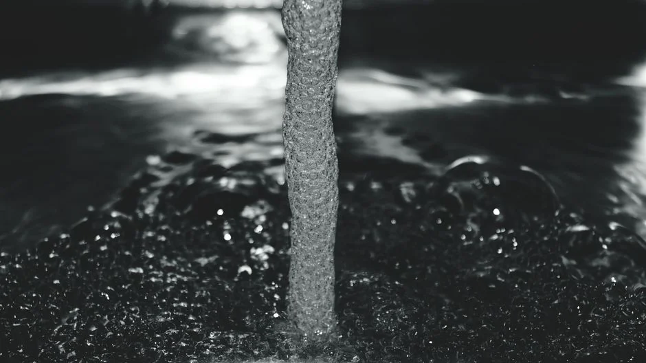
The third stage grows the ultrafine gangue into a floc that DAF bubbles can actually attach to. The two-reagent pair is standard for copper mill water:
| Reagent | Type | Dose Range | Function |
|---|---|---|---|
| Ferric chloride (FeCl₃) | Primary coagulant | 30–80 mg/L | Neutralizes colloid charge, forms Fe(OH)₃ microfloc |
| Alum (Al₂(SO₄)₃·14H₂O) | Alternative coagulant | 50–120 mg/L | Works at narrower pH band 6.0–7.5 |
| Anionic polyacrylamide (PAM) | Flocculant, 10–18 MDa | 0.5–2 mg/L | Bridges microfloc into settleable/attachable floc |
Ferric chloride is the default choice because it handles the wider pH band 5.5–8.5 that you actually see at a copper concentrator, and it delivers a tighter, heavier floc than alum at equivalent dose. Alum works but it is fussier about pH and produces more volume of low-density sludge. Dose the coagulant in a rapid-mix chamber at G = 300–700 s⁻¹ for 30–60 seconds, then dose the anionic PAM 30–90 seconds downstream in a separate floc-mix basin at G = 20–75 s⁻¹ for 10–20 minutes. Below G = 300 s⁻¹, coagulant dispersion is incomplete; above G = 700 s⁻¹ the floc you form in the next stage shatters. Below G = 20 s⁻¹ in floc mix, particles never collide; above G = 75 s⁻¹ you shear the floc back to pin floc and the DAF sees the same problem as if you had skipped the stage entirely.
A PLC-controlled chemical dosing skid with flow-paced metering lets the plant track FeCl₃ and PAM consumption in real time and trim the dose as ore grade shifts through the day — the alternative (manual jar tests once per shift) cannot keep up with a copper circuit that swings feed grade by 30% inside four hours.
Pretreatment Stage 4: Equalization and Optional Lamella Polishing
The fourth stage buffers the rest of the train. Specify a 4–8 hour equalization basin with mechanical mixing between the floc basin and the DAF. The buffer dampens surges from the thickener, evens out pH and coagulant residual, and protects the DAF from hydraulic shock that would push solids straight through the float cell without attachment.
Decision rule on a lamella clarifier: if the post-coag–floc TSS exceeds 1,500 mg/L, install a lamella clarifier ahead of the DAF to cut solids below 500 mg/L. Surface loading on this service is 20–40 m/h — well above conventional clarifiers — because the floc is already pre-conditioned and only needs a polishing pass. If the post-coag–floc TSS is already under 800 mg/L, the clarifier can be skipped and the water feeds the DAF directly, saving CAPEX on smaller plants or on concentrators with cleaner upstream thickener performance. Lamella polishing also reduces downstream coagulant demand by up to 30% by removing the bulk solids before the DAF polish stage, which is a meaningful OPEX line at 50–80 mg/L FeCl₃ dosing.
Matching the DAF to the Pretreated Feed
With the four pretreatment stages online, the DAF sizing inputs tighten considerably. For copper mill water in 2026, the working envelope is:
- Recycle ratio: 10–25%
- Saturator pressure: 5–7 bar
- Hydraulic loading: 10–25 m/h
- Throughput range: 4–300 m³/h on a DAF model train
Expected performance on a properly pretreated feed: TSS removal 85–95%, residual froth/oil capture above 90%, and dissolved copper below 0.5 mg/L courtesy of the upstream sulfide precipitation stage. The Durban University of Technology study is the reference for the operating philosophy — continuous, optimized, and tuned for industrial flow rather than batch treatability. A DAF system matched to this envelope is the right unit operation to specify. If you are sizing across multiple regulatory regimes, the Industrial Wastewater Treatment in Taiwan 2026: Engineering Guide with Compliance, Costs & Equipment Checklist is a useful cross-check on the compliance side.
Troubleshooting: When DAF Still Underperforms
Even with pretreatment in place, three alarms account for most post-installation service calls. The matrix below maps the symptom to the cause and the fix.
| Symptom | Likely Cause | Fix |
|---|---|---|
| Froth too thin, watery float | Residual xanthate poisoning micro-bubbles | Add an oxidation stage (ClO₂ or H₂O₂) upstream of the DAF to break the collector |
| Milky effluent, high TSS in overflow | Floc sheared in transfer piping | Lower pipe velocities below 1.0 m/s; add elbows with larger radius; check floc-mix G is under 75 s⁻¹ |
| Copper breakthrough in DAF effluent | pH drifted above 7.8, CuS re-dissolving | Recalibrate pH dosing pumps; verify sulfide dose is still 1.2–1.5× stoichiometric |
For routine operational checks, the DAF Oil Water Separator Maintenance Guide: Preventative Protocol & Troubleshooting covers saturator pressure decay, nozzle fouling, and scraper torque limits.
Frequently Asked Questions
What pH setpoint does copper concentrator water need before DAF?
The water must be at pH 6.5–7.5 when it enters the DAF. Below 6.0, CuS re-dissolves; above 8.0, the same reaction reverses and rising bubbles carry copper into the float. Trim with sulfuric acid, not HCl, to protect 904L stainless saturator internals from chloride attack.
How much ferric chloride and anionic PAM does copper mill water need?
Dose ferric chloride at 30–80 mg/L as the primary coagulant, then dose anionic polyacrylamide (10–18 MDa molecular weight) at 0.5–2 mg/L 30–90 seconds downstream in a separate floc-mix basin. Outside these windows, floc either shatters in mixing or stays too small for DAF bubble attachment.
Can DAF remove dissolved copper from concentrator water?
No — DAF is a physical separation process for suspended solids and attached particles. Dissolved copper must be precipitated first as CuS at pH 6.5–7.5 using NaHS or Na₂S dosed at 1.2–1.5× stoichiometric. This recovers 95%+ of dissolved copper and produces a saleable CuS sludge.
When do I need a lamella clarifier ahead of the DAF?
Install a lamella clarifier when post-coag–floc TSS exceeds 1,500 mg/L. Surface loading of 20–40 m/h brings solids under 500 mg/L and reduces downstream DAF loading. If TSS is already under 800 mg/L after coagulation–flocculation, the clarifier can be skipped on smaller plants.
What recycle ratio and saturator pressure should I specify for copper mill DAF?
Specify 10–25% recycle ratio and 5–7 bar saturator pressure for copper concentrator service. Hydraulic loading should sit at 10–25 m/h across the DAF cell, matched to a unit sized for 4–300 m³/h. These are the 2026 working envelopes for pretreated thickener overflow and tailings water.