What 'No Civil Works' Really Means for a Containerized MBR
A containerized MBR STP at a factory still needs a defined civil scope: a reinforced-concrete foundation pad sized to the loaded ISO container (roughly 25–32 tonnes per 20 ft unit), an inlet screening manhole, an upstream equalization buffer of 4–8 hours of peak flow, sludge storage or a dewatering skid interface, a clarified-effluent disposal line, and the electrical DB plus cable routing to the container. The MBR product line covers 10–2,000 m³/day (per HydropureWater MBR catalog, 2026), so this civil guide applies from a single 20 ft unit up to a 40 ft frame with parallel trains.
The phrase "no civil works" refers strictly to the elimination of cast-in-place biological tanks, secondary clarifiers, and aeration basins. A factory-tested containerized MBR system arrives with the anoxic/aerobic reactor, submerged PVDF membrane cassette, permeate pump, air blower, and PLC pre-assembled and wet-tested inside a single ISO 20 ft or 40 ft frame. The pad, interconnecting pipework, headworks, and utilities remain site responsibility, which translates into five civil work packages that every factory must complete before the container is lifted off the truck.
Foundation Pad, Access Road, and Crane Hardstand
The pad is the single largest civil cost and the easiest item to under-specify. A fully loaded 20 ft ISO container holding a membrane tank, cassettes, and process water weighs 25–32 tonnes; a 40 ft frame reaches 40–55 tonnes. Each DF-series MBR cassette (80–225 m², per HydropureWater module data) adds 0.8–1.2 tonnes to the operating load, so the slab must be designed for the wetted, not dry, weight.
Pad dimensions track the ISO footprint: 6.06 m × 2.44 m for a 20 ft unit, 12.19 m × 2.44 m for 40 ft. Add 1.0 m perimeter clearance on three sides for pipe manifolds and 0.5 m service access on at least one long side. Pad thickness is a minimum 150 mm of RC30 concrete on 150 mm of Type 1 sub-base; on soils with CBR below 5%, increase to 200 mm with A393 mesh reinforcement to distribute point loads from the corner castings (ISO 1161). Surface tolerance must be specified at ±5 mm over 6 m so the membrane cassette rack stays plumb — anything worse and the air-scour distribution goes uneven within the first month of operation.
Adjacent to the pad, a crane hardstand of at least 6 m × 8 m rated for 40 tonnes is required for a 30-tonne mobile crane offload, plus a 4 m wide all-weather access road from the site gate. The crane radius for a 20 ft lift at 6 m is typically 8–10 m, so a turning bay at the pad end saves half a day on rigging day.
| Item | 20 ft ISO Container | 40 ft ISO Container |
|---|---|---|
| Footprint (container only) | 6.06 m × 2.44 m | 12.19 m × 2.44 m |
| Pad footprint (with clearance) | 8.0 m × 4.0 m | 14.0 m × 4.0 m |
| Operating load (wetted) | 25–32 tonnes | 40–55 tonnes |
| Pad thickness (CBR ≥ 5%) | 150 mm RC30 + 150 mm sub-base | 200 mm RC30 + 150 mm sub-base |
| Pad thickness (CBR < 5%) | 200 mm + A393 mesh | 250 mm + A393 mesh |
| Surface tolerance | ±5 mm over 6 m | ±5 mm over 6 m |
| Crane hardstand | 6 m × 8 m @ 40 t | 6 m × 10 m @ 60 t |
Inlet Screening, Flow Splitter, and Equalization Buffer
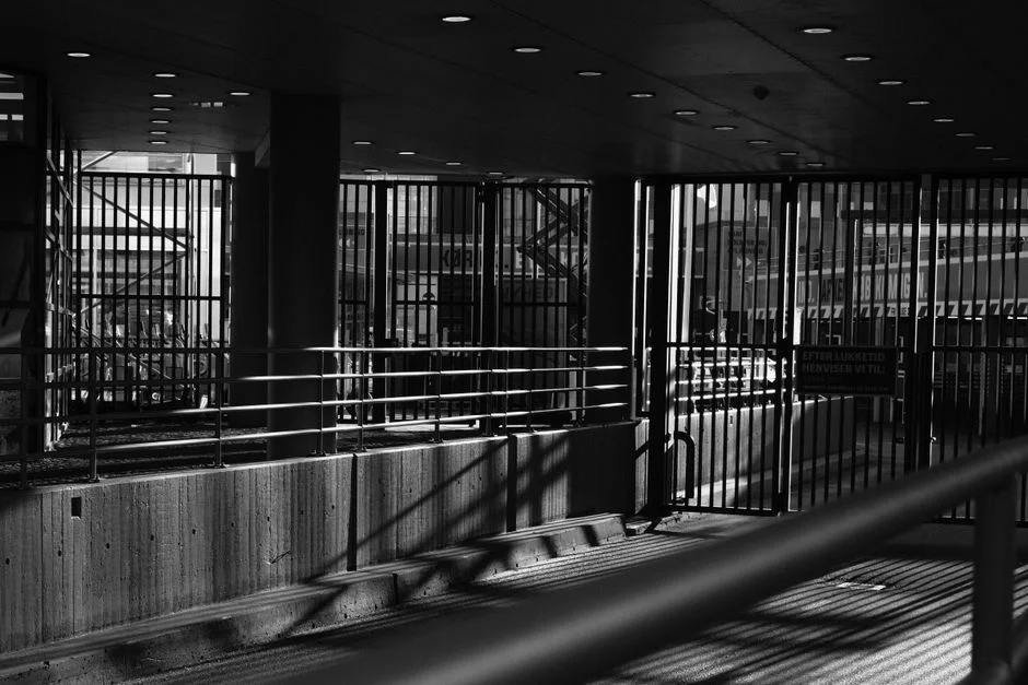
Headworks civil work is what protects the membrane cassette from rags, grit, and hydraulic shock — and it is the package most often skipped on a "plug-and-play" sale. Without it, the first six months of operation will pinhole the permeate pump and blind the cassettes.
Inlet screening is the first item: a rotary bar screen for MBR headworks in a 1.5 m × 1.0 m pre-cast concrete chamber, or a manual bar screen with 5–10 mm clear openings for flows under 20 m³/h. Specify the chamber invert 0.6 m below the inlet pipe soffit so the screen runs drowned and the upstream sewer does not suck air. For multi-train installations, a 1.2 m × 1.2 m × 1.5 m flow splitter with a V-notch weir or a PVC tee is mandatory; uneven feed splits will cause one train to overload and the other to starve, and the operating cost of that imbalance shows up in six months of elevated MLSS in one reactor.
The equalization buffer is the most-skipped civil item in factory MBR projects. Shift-batch discharge from cleaning, CIP, and wash-down cycles can deliver 2–4× the average hourly flow inside a 30-minute window. Size the EQ tank at 4–8 hours of average daily flow, 3–4 m deep, with a submersible mixer rated at 4–6 W/m³ to prevent short-circuiting and septicity. Use bolted glass-fused-to-steel or pre-cast concrete — do not use plastic-lined earthen ponds for factory MBR feed, because the diurnal temperature swing (often 12–18 °C in tropical factory sites) crashes biology in the upstream train. On tight pad sites, the WSZ underground package unit can bury the EQ chamber under a parking lot, freeing the surface footprint for the membrane train.
Effluent Discharge, Sampling Manhole, and Sludge Interface
Downstream civil scope is where compliance is won or lost. MBR permeate at sub-1 μm filtration (per HydropureWater MBR permeate spec) typically delivers BOD ≤ 5 mg/L, COD ≤ 30 mg/L, TSS ≤ 2 mg/L, and turbidity ≤ 1 NTU, which clears direct-discharge thresholds under most jurisdictions including Taiwan EPA, India CPCB, and China GB 18918-2002 Grade 1A. The civil work below the container simply has to deliver that water to the right outfall and prove it on demand.
A 1.0 m × 1.0 m sampling manhole on the permeate line, 2–3 m downstream of the container, fitted with a 24-hour composite auto-sampler, is the factory's compliance point in roughly 95% of discharge permits. The discharge pipe itself is minimum DN100 uPVC or HDPE at a 1:200 slope, terminating in the factory outfall, irrigation storage pond, or recycling cistern; a non-return valve on the line prevents storm backflow from contaminating the permeate side of the membrane cassettes.
Sludge handling is the civil package that ties back to the front of the plant. A 5–10 m³ concrete or PE sludge storage tank, sized for 7–14 days of waste activated sludge (WAS) at 0.3–0.5% solids, sits between the MBR waste-sludge draw-off and the dewatering skid. The dewatering interface itself is a plate-and-frame filter press for WAS dewatering sized to the WAS volume (1–500 m² chamber area available), or a decanter centrifuge for higher throughput. Where chemical sludge from a co-treatment stream (for example, a DAF unit on a beverage line — see the beverage wastewater MBR engineering guide) feeds the same sludge train, a lamella clarifier thickens the combined stream before the press. None of this equipment ships inside the container; the civil scope must allocate pad and pipework for it.
Electrical DB, Cable Routing, and PLC Tie-In
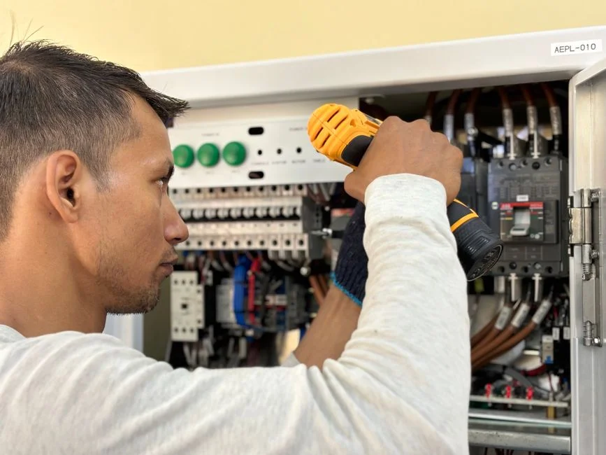
Electrical civil scope is typically undersized on a containerized project because the container "comes with controls." It does — but it still needs a dedicated feeder, a distribution board within reach, and clean instrumentation cabling back to the EQ tank and flow meter.
Power supply is 380–415 V three-phase 50 Hz on a dedicated feeder, with the MBR drawing 0.6–1.2 kWh per m³ treated (HydropureWater field data, 2026, on the DF-series submerged cassette). The factory installs a wall-mounted distribution board within 5 m of the container, with motor-rated breakers for the permeate pump, air blower, and sludge pump — typically 1.5–7.5 kW total connected load, with the blower as the largest single item. A separate MCC room is not required for a single container; a 600 mm × 400 mm cable trench carrying 100 mm uPVC conduit runs from DB to the container junction box, with one conduit for power and a second for instrumentation to keep VFD noise off the 4–20 mA level signals.
Instrumentation tie-ins are short. The factory supplies the level transmitter cable run for the EQ tank (typically 20–50 m of 2-core shielded) and the flow meter on the permeate line; the MBR PLC inside the container reads both via 4–20 mA and uses them for pump start/stop and backwash trigger logic. Earth the pad to ≤ 1 Ω and bond to the container chassis; on exposed factory sites add lightning protection per IEC 62305. For a deeper look at how the electrical and PLC interfaces typically price into a project, the MBR system cost and ROI engineering guide walks through a 200 m³/day Taiwan factory case study with the same civil split.
Typical Civil Schedule, Cost Band, and Pre-Arrival Checklist
On a 10–500 m³/day containerized MBR, civil works for the five packages above typically run 3–8% of total project CAPEX. The composition is roughly 35–45% on the pad and crane hardstand, 25–30% on the EQ tank and headworks, 15–20% on pipework, and 10–15% on the electrical DB and cable trench. Schedule-wise, plan on pad pour plus 7-day concrete cure, 5–7 days for the EQ tank and headworks, and 3–5 days for pipework and electrical — a total of 14–21 days of civil work before the container is delivered and craned in.
The container itself arrives factory-tested, so on-site commissioning is 1–2 days of influent seeding and PLC verification versus 2–3 weeks for a built-in-place STP. That delta is where the "no civil works" claim is real — but only after the pad, headworks, EQ, sludge, and electrical packages are already behind you.
| # | Pre-Arrival Checklist Item | Done? |
|---|---|---|
| 1 | Foundation pad poured, cured ≥ 7 days, surveyed to ±5 mm over 6 m | ☐ |
| 2 | EQ tank hydro-tested, mixer installed and rotation-checked | ☐ |
| 3 | Inlet bar screen installed, invert level verified against inlet pipe | ☐ |
| 4 | Permeate discharge DN100 line terminated at outfall with non-return valve | ☐ |
| 5 | Sampling manhole complete with 24-hour composite auto-sampler | ☐ |
| 6 | Power feeder live at DB, phase rotation checked, megger test on cables | ☐ |
| 7 | Crane hardstand compacted, 4 m access road drained and gated | ☐ |
| 8 | Wash-down water tap within 10 m of container for cassette cleaning | ☐ |
| 9 | Sludge storage tank installed, draw-off line tested back to the WAS pump | ☐ |
| 10 | Operator PPE issued, PLC HMI password handed over, logbook opened | ☐ |
Frequently Asked Questions
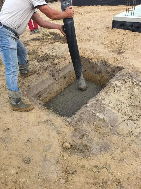
What pad thickness is required for a 20 ft containerized MBR?
A 20 ft unit weighs 25–32 tonnes wetted, so a minimum 150 mm RC30 slab on 150 mm of Type 1 sub-base is required for soils with CBR ≥ 5%; increase to 200 mm with A393 mesh reinforcement for CBR < 5%, and keep surface tolerance to ±5 mm over 6 m so the DF-series MBR cassette rack stays plumb.
How do I size the EQ tank for a factory with shift-batch discharge?
For shift-batch discharge, size the EQ tank at 4–8 hours of average daily flow at 3–4 m depth, with a submersible mixer rated at 4–6 W/m³, using glass-fused-to-steel or pre-cast concrete to avoid temperature swing that crashes upstream biology.
Does a containerized MBR need a separate MCC room?
No separate MCC room is needed for a single container; a wall-mounted distribution board within 5 m of the container, with motor-rated breakers for the 1.5–7.5 kW total connected load, is sufficient — provided the cable run uses separate power and instrumentation conduits.
What extra earthworks are needed for poor soil at the pad location?
On soils with CBR < 5%, remove the topsoil to 300 mm, lay a 150 mm Type 1 sub-base compacted to 95% modified Proctor, then pour 200 mm of RC30 with A393 mesh — this typically adds 3–5 days and 8–12% to the pad cost versus a normal-soil pad.
How long do civil works take before the container arrives?
Plan on 14–21 days: 7 days for pad pour and cure, 5–7 days for the EQ tank and headworks, and 3–5 days for pipework and electrical tie-in, with the container lift and 1–2 day commissioning scheduled immediately after cure.