What Inclined Plate Settler Sizing for Industrial Wastewater Involves
Inclined plate settler sizing for industrial wastewater is design flow Q divided by surface overflow rate vo on projected plate area. Conservative polymer-dosed designs run at 5–10 m/h. High-rate units with flocculation and sludge recirculation reach 20–40 m/h. A 200 m³/h stream needs 20 m² of effective plate area at 10 m/h, inside a tank plan of roughly 80–90 m².
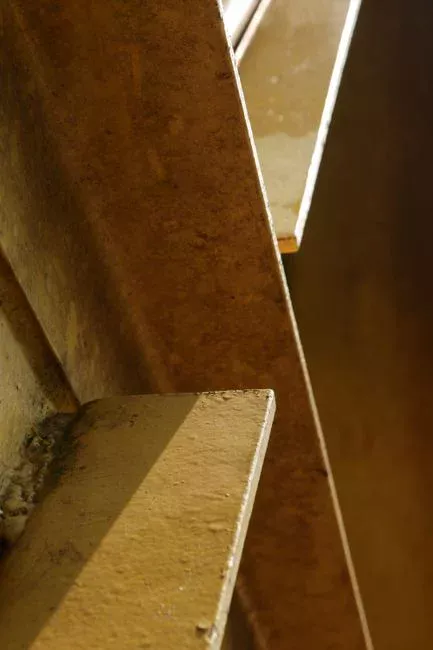
An inclined plate settler — also called a parallel plate settler, or a tube settler when hexagonal channels are used — stacks 55–60° plates inside a compact tank. Solids settle across the short perpendicular gap between plates (50–80 mm) and slide into a sludge hopper. Clarified water rises counter-current or cross-current to an outlet launder.
The core relationship is A = Q / vo, where Q is design flow (m³/h) and vo is surface overflow rate (m/h). That Hazen-style rate is applied to projected plate area, not tank surface, so the settling path is the perpendicular gap rather than tank depth. A 60° plate pack of 40 m² projected area fits a tank plan of roughly 80–90 m² instead of the 400+ m² a conventional clarifier would need for the same 200 m³/h load. Chemistry enters only through coagulant dose and the chosen vo, not through the plate area itself.
Packaged module geometry is documented on the High-Efficiency Sedimentation Tank (Lamella Clarifier) datasheet. For a process overview of a packaged lamella clarifier, use that engineering explainer before you freeze hydraulic area.
Minimum Flow Rate Across Lamella Settler
Minimum flow rate across lamella settler channels is set by sludge-sliding and laminar-flow limits, not by catalogue nameplate alone. Most plants we size for industrial pre-treatment keep channel velocity high enough that settled solids keep moving at 55–60°, yet low enough that Re stays near or below 500–1,000 after geometry correction. Running far below the design Q lets sludge rest on the plates, then re-suspend on the next peak. Running above the design vo without coagulant cuts TSS capture.
Treat the datasheet Qavg and Qpeak as a working band, and ask the vendor to certify performance at both ends. How the inclined plates separate solids in the first place is covered in our lamella clarifier working principle guide.
For a conservative industrial unit at vo = 5–10 m/h, the practical lower end of continuous operation is often about 40–60% of Qavg before sludge motion becomes unreliable. Below that band, intermittent blowdown and steeper hopper slopes matter more than shrinking the plate pack. The upper end remains Qpeak with peaking factors of 1.5–2.0 on industrial dry-weather flow. Confirming minimum flow rate across lamella settler duty on the enquiry sheet prevents overnight idle fouling on batch plants.
The Four Engineering Inputs That Drive Settler Capacity
Every sizing calculation starts with four numbers: design flow Q, surface overflow rate vo, plate angle θ, and effective-area ratio ε. Get any of these wrong and the unit will short-circuit on peak flow or carry far more capital cost than needed.
Design flow Q (m³/h). For industrial streams, multiply average dry-weather flow by a peaking factor of 1.5–2.0 to capture shift discharges, CIP surges, and batch dumps. Always list both Qavg and Qpeak on the datasheet. A unit sized only on the average fails on the first peak event.
Surface overflow rate vo (m/h). This is the most leveraged design choice. Use 2–5 m/h for raw municipal primary clarification without coagulant. Use 5–10 m/h for industrial pre-treatment (textile, food, metal finishing) with polymer dosing. Use 20–40 m/h for high-rate chemical or biological sludge separation with flocculation and sludge recirculation.
Pushing above 10 m/h without coagulant and sludge recirculation produces poor TSS removal and a thick, hard-to-handle underflow. That high-rate configuration matches the high-efficiency sedimentation tank catalogue module. Published potable-water standards show how conservative regulators get when no site data exists. The Great Lakes Board's Recommended Standards for Water Works (2007 Edition) caps tube settlers at a maximum rate of 2 gpm per square foot of cross-sectional area (4.8 m/hr). The same document sets a maximum plate loading rate of 0.5 gpm per square foot (1.2 m/hr), based on 80 percent of the projected horizontal plate area. Higher rates are allowed only after successful pilot-plant or in-plant demonstration studies.
Plate angle θ (°). The industry standard is 55–60° from horizontal. Below 55°, the tangential gravity component along the plate is too low and sludge piles up instead of sliding. Above 60°, projected horizontal area shrinks through the cos θ term, and most manufacturers settle on 60° as the geometric optimum.
Effective-area ratio ε (dimensionless). Only 50–70% of the gross inclined plate area is hydraulically usable; the remainder is lost to inlet and outlet zones, plate support frames, sidewall clearances, and flow-distribution channels. Always ask the supplier for the certified ε of the specific module — do not accept "typical 0.6" without a test sheet. Detailed plate spacing and module dimensions also appear in the inclined plate settler specifications guide.
| Parameter | Symbol | Conservative industrial | High-rate industrial | Municipal primary |
|---|---|---|---|---|
| Surface overflow rate | vo (m/h) | 5–10 | 20–40 | 2–5 |
| Plate angle | θ (°) | 55–60 | 60 | 55–60 |
| Plate spacing | s (mm) | 60–80 | 50–60 | 80 |
| Effective-area ratio | ε | 0.55–0.60 | 0.65–0.70 | 0.50–0.55 |
| Coagulant/flocculation | — | Optional polymer | Required + sludge recirculation | None |
Step-by-Step Sizing Calculation: A 200 m³/h Worked Example
Here is the procedure to size an inclined plate settler for a 200 m³/h industrial stream. You can copy the same four steps onto any flow between 50 and 500 m³/h by swapping Q.
Step 1 — Required effective plate area. Choose vo = 10 m/h for a conservative industrial design with polymer dosing. A = Q / vo = 200 / 10 = 20 m² of effective horizontal projected plate area. This is the area that actually does the settling.
Step 2 — Plate-angle correction. The 20 m² is the horizontal projection; to get the gross inclined plate area, divide by cos θ. At θ = 60°, cos 60° = 0.5, so the gross inclined area is 20 / 0.5 = 40 m² of plate pack. The plates themselves must be physically 40 m² when laid out at 60° inside the tank.
Step 3 — Apply the effective-area ratio. The plate pack occupies a tank footprint of 40 / ε; with ε = 0.6, that gives roughly 67 m². Add the inlet zone (typically 15–20% of plan area) and the outlet launder, and total tank plan area lands at roughly 80–90 m². For comparison, a conventional clarifier at 1 m/h would need 200 m², so the plate pack saves ~55–60% of the footprint even at the conservative vo.
Launder length has a published ceiling too. According to the Great Lakes Board's wastewater standards (2014 edition), weir loadings shall not exceed 20,000 gpd/lin ft at design peak hourly flow for plants of 1 mgd or less. Larger plants are capped at 30,000 gpd/lin ft, about 375 m³/m·d in metric. Check the plate-settler outlet launder against those numbers before you freeze tank dimensions.
Step 4 — Sludge hopper and underflow sizing. The hopper must hold at least 8–24 h of sludge production between blowdowns. For a 2% solids underflow at 200 m³/h with 95% TSS capture from 500 mg/L influent, sludge production is roughly 0.5–1.5 m³/h of thickened sludge (HydropureWater field data, 2025-09). Specify a hopper with 30° side slopes, bottom access for a pump or blowdown valve, and a plate-to-sludge clearance of at least 0.5–1.0 m to prevent re-suspension.
High-rate alternative. Push vo to 30 m/h with coagulant dosing and sludge recirculation. The same 200 m³/h stream then needs only A = 6.7 m² of effective plate area. Tank footprint falls to roughly 25–30 m² — about one-third the conservative design. That regime is standard for metal-finishing and FOG streams where flocculation is already in place.
Plate Geometry, Hydraulics, and Why Laminar Flow Matters
Plate-pack channels must stay near laminar flow; otherwise eddies re-suspend settled solids and the unit underperforms by 30–50%. Keep Reynolds number Re < 500 across the channel. Calculate Re = vchannel × Dh / ν, where Dh is hydraulic diameter and ν is kinematic viscosity of water (~1 mm²/s at 20 °C).
A worked check for a 50 mm plate gap at vo = 10 m/h starts with average channel velocity. That velocity is vo / (3600 × s) = 10 / (3600 × 0.05) ≈ 0.056 m/s, giving a crude Re around 2,800. Hydraulic diameter of a wide rectangular channel is roughly 2s, about 100 mm here, and effective velocity parallel to the plates is 2–5× lower after inclined geometry is applied. Corrected Re lands in the 500–1,000 band, which is acceptable for plate-settler operation.
Particle settling velocity sets the upper bound on vo. Stokes' law for a 50 µm quartz particle (ρs = 2.65 g/cm³) in 20 °C water gives vs ≈ 1.7 m/h, so capturing that particle without flocculation requires vo ≤ 1.7 m/h. Most industrial designs therefore dose coagulant to grow flocs above 100 µm and unlock the 5–10 m/h band, while the 20–40 m/h band needs both polymer and sludge recirculation. Plate spacing below 50 mm risks clogging with biological or fibrous solids, and above 80 mm the channel behaves more like a conventional settler, collapsing the footprint benefit.
If the upstream stream carries FOG, oil, or buoyant colloids, a dissolved air flotation system is the right primary unit, with a plate settler as a polishing stage.
Conservative vs High-Rate Lamella Clarifier Sizing: How to Choose the Band
Clarifier selection for industrial wastewater starts with particle buoyancy and target TSS, then moves to primary versus secondary duty and sludge handling. Choose an inclined plate settler when solids settle after coagulation: metal hydroxides, flocculated chemical sludge, and many textile or food TSS loads. Choose DAF when oil, grease, FOG, or buoyant colloids dominate. Use a conventional circular or rectangular clarifier when land is cheap, solids are dense, and you need large sludge inventory rather than a compact plate pack.
Conventional primary tanks give the benchmark for that comparison. According to the Great Lakes Board's Recommended Standards for Wastewater Facilities (2014 edition), primary settling tanks are rated at 1,000 gallons per day per square foot (41 m³/m²·d) at design average flow. That loading rises to 1,500–2,000 gallons per day per square foot (61–81 m³/m²·d) at design peak hourly flow for tanks not receiving waste activated sludge. The same standard requires sizing for both flow conditions and building to the larger surface area, and it notes roughly one-third BOD removal at the average loading.
Primary duty (raw or chemically pretreated feed) usually runs at lower vo, 2–10 m/h depending on coagulant. Secondary or tertiary polishing after biological treatment can run higher rates if flocs are strong. Energy use on a gravity plate settler is mostly feed pumping and sludge transfer, while DAF adds recycle-pump and air-saturator power.
Thick hydroxide underflow needs an oversized hopper (30–50% extra volume), and light biological solids may need continuous scrapers. Buyers who ask how high the turbidity a lamella clarifier can treat should size on floc strength and certified vo, not turbidity alone. Capex comparisons should separate hydraulic area from lamella clarifier cost drivers such as plate material, hopper volume, and sludge handling.
Surface Overflow Rate for Industrial Pre-Treatment Design
There is no single correct vo; the right number depends on what is in the water and what chemistry is already upstream. The table below maps realistic operating bands to common application classes. Treat the values as starting points for a vendor datasheet, not as fixed specifications.
| Application | vo (m/h) | Plate spacing (mm) | ε | Notes |
|---|---|---|---|---|
| Municipal primary clarification | 2–5 | 80 | ~0.55 | No coagulant; conservative footprint |
| Industrial pre-treatment (textile, food, metal finishing) | 5–10 | 60–80 | ~0.60 | Polymer dosing; standard EPC spec |
| High-rate chemical or biological sludge separation | 20–40 | 50–60 | 0.65–0.70 | Flocculation + sludge recirculation required |
| Heavy metals precipitation or cooling-tower blowdown | 8–12 | 60 | ~0.60 | Thick underflow; oversize hopper by 30–50% |
For grinding wastewater and other coagulation-sedimentation streams, cross-check the parameters above against the coagulation-sedimentation engineering guide. That guide documents influent TSS bands, polymer dose ranges, and sludge yield numbers used in current 2026 equipment designs.
Common Sizing Mistakes and How to Avoid Them
Most field failures of correctly calculated plate settlers trace back to one of four omissions at the datasheet stage.
Mistake 1 — Sizing only on average flow. A unit sized on Qavg will fail on the first peak hourly event, because most underperformance shows up on the peak, not the average. Specify Qpeak in the enquiry and ask the vendor to confirm performance at peak flow, not just at the design point.
Mistake 2 — Ignoring the inlet zone. The inlet must spread flow across the full tank width via a wide overflow weir or perforated baffle, per the equal-flow-distribution guidance in Schmitz's 2019-12 Smart Water Magazine tube settler guideline. Short-circuiting at the inlet reduces effective area by 30–50% and is the single most common cause of an under-performing plate pack. Dye testing showed only three of the seven plate pitches received the maximum SOR input of 0.57 m³/m²·h, according to a 2021 IJRASET study of an inclined-plate clarifier. Maldistribution, not the area calculation, set the real capacity.
Mistake 3 — Plate-to-sludge-zone gap too small. Re-suspension of settled sludge back into the effluent is the most common field failure mode. Keep at least 0.5–1.0 m between the bottom of the plate pack and the sludge hopper crown, and verify hopper-inlet velocity stays below 0.05 m/s to avoid scouring.
Mistake 4 — Omitting coagulant for high-rate operation. vo above 10 m/h without dosing produces poor TSS removal — typically only 40–60% on a 500 mg/L industrial feed. Budget for upstream flocculation or a DAF stage when targeting the 20–40 m/h band. The effluent TSS exceedance engineering guide documents dose-response curves and common failure modes when chemistry and hydraulics are misaligned.
Sizing Checklist You Can Hand to a Supplier
Use this five-row table as the cover sheet for any plate-settler enquiry. A vendor who cannot fill in every row on certified data is not yet ready to quote.
| # | Parameter | Your value | Vendor certified value |
|---|---|---|---|
| 1 | Qavg / Qpeak (m³/h) | — | — |
| 2 | Influent TSS / target effluent TSS (mg/L) | — | — |
| 3 | Plate angle θ / plate spacing s / effective-area ratio ε | — | — |
| 4 | Recommended vo for your TSS band (m/h) | — | — |
| 5 | Inlet-zone, outlet-zone, and plate-to-sludge clearance (m) | — | — |
Confirm influent temperature range and the coagulant/flocculant dose already in place upstream, since both shift the achievable vo by 20–40%. Request the manufacturer's CFD or tracer-test report showing flow distribution at peak flow — the absence of that report is the single best indicator that a quote is a catalogue number, not an engineered selection.
Sanity-check any footprint claim against vendor-published data as well. Meurer Research, a plate-settler specialist, states its inclined plate settlers deliver up to 80% smaller footprint than open basin clarifiers. The same source reports effective settling area increasing by up to eight times. Those figures bracket the 5–10× footprint reduction calculated above for a 60° pack at conservative rates, so treat bigger promises as a request for test data.
Who This Is For and the Next Step
This guide is for plant engineers, EPC designers, and procurement teams sizing industrial or municipal inclined plate settlers from 50 to 500 m³/h. Look elsewhere if your solids float rather than settle, or if influent TSS stays above about 4,000 mg/L without pre-thickening. Inclined plate settler sizing for industrial wastewater only pays off when the four inputs above carry certified values; everything else is tank steel. When you have Qavg, Qpeak, TSS in/out, and upstream chemistry ready, send them through the inclined plate settler sizing enquiry form for a checked plate-area and footprint proposal.
Frequently Asked Questions
What surface overflow rate should I use for industrial wastewater?
Default to 5–10 m/h with polymer dosing for industrial pre-treatment. Push to 20–40 m/h only when flocculation and sludge recirculation are already in the upstream process train. Without that chemistry, high-rate operation usually drops TSS removal into the 40–60% range on a 500 mg/L feed. Keep the peaking factor of 1.5–2.0 on the same datasheet so the chosen vo still holds at Qpeak.
How small can an inclined plate settler be for 50 m³/h?
At vo = 10 m/h, required effective plate area is 50 / 10 = 5 m². Including inlet zone, outlet launder, and sludge hopper, the realistic tank footprint is 12–18 m². High-rate designs with sludge recirculation can shrink further, but only with confirmed flocculation upstream and a certified effective-area ratio on the module.
When do I need a DAF instead of a plate settler?
Use a DAF for oil and grease, FOG, or buoyant colloids where particles float rather than settle. Use an inclined plate settler for settleable suspended solids, metal hydroxides, and flocculated chemical sludges. Many plants place DAF first and a plate settler as polish when both floating and settling fractions are present in the same train.
What influent TSS is too high for an inclined plate settler?
Above roughly 4,000 mg/L the plate pack risks rapid fouling. Pre-thicken with a DAF or gravity thickener first to bring the feed below 4,000 mg/L and protect the plate channels. Also keep plate spacing at 60–80 mm on fibrous or biological solids to reduce bridging inside the pack.
What design criteria matter most for primary versus secondary duty?
Primary industrial duty usually sizes on vo = 5–10 m/h, peaking factor 1.5–2.0, and certified effective-area ratio ε. Secondary or high-rate chemical sludge duty can use 20–40 m/h only with flocculation and sludge recirculation. In both cases, inlet distribution and 0.5–1.0 m plate-to-sludge clearance decide whether the calculated area actually performs in the field.