Why paint shop pretreatment is non-negotiable before a DAF
A dissolved air flotation system only removes what has already been conditioned into a floatable floc; raw paint overspray, solvents, and surfactants defeat micro-bubble attachment and pass straight through (Filtox, 2025). Skipping or under-sizing the train that sits ahead of the DAF produces four specific, expensive failures rather than a vague efficiency loss:
- E-coat bath rejection: pH drift below 6.0 or above 9.0, or conductivity spikes above 2,000 µS/cm, destabilise the electrodeposition bath and force disposal of an entire batch — typically 40–80 m³ of cathodic epoxy at €8,000–€15,000 per dump.
- Fisheye and crater defects: particulate carryover from under-conditioned DAF effluent creates coating rejects on otherwise saleable bodies; fisheye rates above 0.3% on a Tier-1 line translate to 30+ rework bodies per shift.
- Pump and nozzle fouling: rags, overspray chunks, and masking tape fragments that bypass screening rag the air-saturation vessel and erode nozzle headers, cutting service life from a typical 5–7 years to under 18 months.
- Sludge volume inflation: a poorly detackified feed delivers 3–5× more sludge mass to the downstream filter press, raising disposal cost from roughly €80/dry tonne toward €300/dry tonne for hazardous waste.
The recirculation economics make the case cleanly: 70–90% rinse-water reuse — the standard automotive water-recovery target — is only achievable with an intact pretreatment train, and that train has a confirmed sequence: chemical conditioning first, then DAF clarification, then sludge dewatering (ALAR, 2025). Treat the DAF as the middle of a three-link chain, not as a stand-alone clarifier.
Stage 1 — Screening and grit removal at the booth recirculation tank
The first physical barrier is a coarse screen installed in or directly above the booth recirculation tank. Its job is to protect transfer pumps, the DAF recycle pump, and the nozzle headers from rags, overspray chunks, masking tape, weld splatter from the body shop, and shop floor debris that routinely ends up in the pit.
For booth water, specify a rotary drum or travelling water screen with 1–3 mm aperture; for e-coat rinse loops that feed the same DAF, drop to 0.5–1.0 mm wedge-wire to catch the fine phosphate carryover that blinds DAF lamella plates. Mount the screen on the suction side of the transfer pump rather than at the DAF inlet — pulling solids through the pump is what kills impellers, not pushing them.
The DAF feed impact is direct: particulate above 200 µm entering the flotation cell causes ragging of the air-saturation vessel and uneven bubble distribution, which shows up as a patchy float layer and cloudy subnatant. This stage is the most commonly missed step in retrofit projects — older booths discharge into a pit with no screening, and the DAF is then forced to act as a de facto screen, which it does badly. A rotary mechanical bar screen sized for the recirculation flow is the standard fix; aperture and basket volume are the two spec numbers to lock at procurement.
Stage 2 — Oil, water and solvent separation
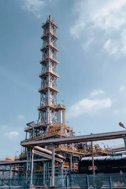
Free and emulsified oil must leave the stream before the DAF, not inside it. Distinguish the two clearly: free oil is skimmed mechanically in a corrugated plate interceptor (CPI) or API separator, with a target of < 50 mg/L leaving this stage; emulsified oil requires a chemical break (coagulant dosing) further downstream and cannot be removed by skimming alone. Both forms originate in the same place — booth lubrication oils, anti-chip coatings dripping from robot wrists, phosphate stage carryover, and compressor condensate discharged into the booth pit.
Residual emulsified oil is the single most common cause of poor DAF performance because oil films coat the floc surface and prevent micro-bubble attachment (Filtox, 2025). The visible symptom is a thin, watery float layer and a DAF effluent that looks clean to the eye but carries 200+ mg/L TSS in the subnatant.
Specify a CPI separator or oil-skimming tank sized for 10–20 minutes of recirculation flow ahead of the equalization basin, with a positive-skimmer drive rather than a weir overflow. The CPI alone is not enough — plan a coagulant dosing point immediately downstream of the oil-removal stage so that the emulsion break happens in a controlled flash-mix chamber rather than chaotically inside the DAF. Discharge the skimmings to a dedicated hazardous-waste drum, not back into the equalization tank.
Stage 3 — Flow and load equalization
Paint shops are batch processes. A primer surge at line start-up, a topcoat colour change, or a booth maintenance drain delivers a shock load in TSS, pH, and solvent concentration — often inside a 15–30 minute window. A DAF fed directly from a batch process is a DAF that is either under-loaded or overloaded, never stable.
Specify an equalization volume of 8–24 hours of recirculation flow, with aerated mixing at a low-intensity G of 5–15 s⁻¹ to keep solids in suspension rather than settled (anaerobic conditions generate H₂S and volatile fatty acids that wreck downstream chemistry). The aeration also strips residual solvents — typically 30–60% of incoming VOC load — before they reach the DAF, where they would otherwise nucleate inside the air-saturation vessel and destabilise the bubble cloud.
Quantify the effect: a feed TSS swing from 300 to 2,000 mg/L collapses DAF float solids because hydraulic retention time inside the cell is fixed; equalization holds the swing to within ±20% of the daily average, which is the band a properly sized DAF can absorb without losing float. The equalization tank also serves as the dosing point for pH correction and coagulant, so locate it at the same elevation as the flash-mix chamber to avoid a second pumping stage.
Stage 4 — pH adjustment and coagulation
Paint detackification is the core chemistry of the train: the goal is to convert sticky, re-dispersible overspray into a non-tacky, hydrophobic floc that the DAF can float rather than re-adhere to passing panels, robot wrists, or pump internals. Two operational levers do the work — pH and coagulant choice.
Hold the DAF feed pH in the 6.5–8.5 window (Filtox, 2025). Below 6.0, the e-coat bath rejects; above 9.0, the same bath rejects in the other direction, and aluminium-based coagulants convert to soluble aluminate and lose 50–70% of their charge-neutralisation capacity. Use NaOH (typically 10–25% solution) or Mg(OH)₂ slurry for up-adjustment, and H₂SO₄ (10–20%) for down-adjustment; both are easy to meter and compatible with downstream e-coat chemistry.
For paint waste, three coagulant families are in production use today:
- Polyaluminium chloride (PAC): 50–150 mg/L as product; best general-purpose choice for waterborne basecoat overspray.
- Ferric chloride (FeCl₃): 80–200 mg/L as product; preferred when phosphate carryover is significant, because Fe³⁺ precipitates phosphate as FePO₄ and removes it in the sludge.
- Cationic polyamines: 5–30 mg/L as product; used as an emulsion-breaking aid ahead of the primary coagulant, particularly when anti-chip or seam-sealer carryover is present.
Residence time is short but defined: 3–10 minutes in a flash-mix chamber at G > 500 s⁻¹ to disperse the coagulant and destabilise the colloid, then 15–30 minutes in a flocculation zone at G = 50–100 s⁻¹ to build a settleable, floatable floc without breaking it. Dose the coagulant through an automatic coagulant and flocculant dosing skid paced by inline pH and TSS probes; manual dosing on a paint line is a mis-spec waiting to happen.
Stage 5 — Flocculation and DAF feed targets
Flocculation completes what coagulation started. A high-molecular-weight (8–18 million Dalton) anionic or cationic polyacrylamide, dosed at 0.1–2 mg/L, bridges primary coagulant particles into a large, low-density floc that 20–80 µm micro-bubbles can lift. Over-dose past 2 mg/L and the floc becomes gelatinous and traps water; under-dose below 0.1 mg/L and the floc stays small, sinks, and exits with the subnatant.
The single procurement-ready artifact of this whole train is the DAF feed parameter table. The numbers below are what the DAF must see at the inlet, not what the booth pit contains, and they are the contract numbers to hand to a vendor.
| Parameter | Target at DAF inlet | Protects |
|---|---|---|
| Total suspended solids (TSS) | < 500 mg/L | Float solids capacity, subnatant clarity |
| Fats, oils & grease (FOG) | < 100 mg/L | Micro-bubble attachment, float integrity |
| pH | 6.5–8.5 | E-coat bath stability, coagulant chemistry |
| Temperature | 15–35 °C | Floc kinetics, DAF hydraulic stability |
| Conductivity | < 2,000 µS/cm | E-coat bath rejection threshold |
| Particle size (post-floc) | 10–100 µm | Bubble attachment efficiency |
| Air-to-solids ratio (A/S) | 0.02–0.06 lb air / lb TSS | Float rise rate, sludge solids % |
| Surfactant load (MBAS) | < 20 mg/L | Floc hydrophobicity, foam at DAF weir |
At these feed conditions, a dissolved air flotation system typically achieves 90–95% TSS removal, 95%+ FOG removal, and a float sludge at 3–6% dry solids — the consistency a plate-and-frame press can handle. The air-to-solids ratio is the operator's primary lever when feed conditions drift: raise recycle pressure from 5 to 6 bar to add bubble volume, or throttle the recycle flow from 30% to 20% of DAF throughput to concentrate the bubble load on a dirtier feed. For a broader review of operating cost and compliance framing, see the DAF system engineering guide for 2026.
Common pretreatment failures and how they show up at the DAF
The DAF is a diagnostic instrument for everything upstream of it. A trained operator can read the float layer and the subnatant and point at the failing stage without leaving the platform:
- Cloudy DAF effluent, normal float: pH out of the 6.5–8.5 band, or insufficient coagulant. Check the inline pH probe first; it drifts faster than the dose pump fails.
- Thin or watery float layer: oil breakthrough from Stage 2, or over-sheared floc from a flash-mix G above 1,000 s⁻¹. Verify CPI skimmer speed and coagulant dose point.
- Grey, sinking sludge instead of float: under-conditioned feed — floc is too dense or too small. Increase flocculant dose and check particle size at the flocculation outlet.
- Air-saturation vessel fouling or ragging: screening stage is missing or has a torn basket. Inspect the screen and clean the recycle pump strainer.
- Foam at the DAF weir: surfactant load above 20 mg/L MBAS, typically from a detergent spill upstream or a failed rinse-stage anti-foam dose.
The pattern: the visible symptom is almost always one or two stages upstream of where it appears. A DAF cannot compensate for feed swings — for the heavy-metals and oil parameters that ride along on this stream, the 2026 heavy metals discharge standard and the 2026 global oil and grease discharge compliance guide set the boundary conditions that pretreatment must hold the DAF feed inside.
Sludge handling downstream of the DAF
Close the loop on solids handling, because pretreatment quality directly sets dewatering cost. Properly detackified, flocculated float sludge dewaters to 25–40% dry solids in a plate-and-frame filter press at 6–8 bar; poorly conditioned sludge sits at 10–15% dry solids, fails to release water, and chokes the press on cycle 3 of every sequence. The standard automotive train ends the same way: DAF float → sludge thickener → filter press → cake disposal (ALAR, 2025).
The economic link is straightforward: every 1% reduction in feed oil and surfactant load translates to roughly 3–4% higher cake solids, which means fewer press cycles, lower polymer conditioning demand, and lower disposal tonnage. A paint line producing 800 kg/dry day of float sludge saves €20,000–€35,000 per year in disposal alone when feed conditioning is held inside the parameter table.
Frequently Asked Questions
What pH range must DAF feed be held inside for an automotive paint shop?
6.5–8.5. Outside this window, aluminium-based coagulants lose charge neutralisation capacity and the e-coat bath rejects, forcing disposal of 40–80 m³ of cathodic epoxy per incident (Filtox, 2025).
What is the typical TSS limit at the DAF inlet for paint overspray?
< 500 mg/L. Equalization of 8–24 hours of recirculation flow holds a raw-stream swing of 300–2,000 mg/L to within ±20% of the daily average, which the DAF can absorb without losing float.
Which coagulant and flocculant families are standard for paint detackification?
Polyaluminium chloride (50–150 mg/L) or ferric chloride (80–200 mg/L) for coagulation, with a cationic polyacrylamide flocculant (0.1–2 mg/L, 8–18 million Dalton) dosed 3–10 minutes downstream in a flocculation zone at G = 50–100 s⁻¹.
What screen aperture protects a DAF recycle pump from booth debris?
1–3 mm for booth recirculation water; 0.5–1.0 mm wedge-wire for e-coat rinse loops that share the same DAF. Particulates above 200 µm rag the air-saturation vessel.
What is the target FOG level at the DAF inlet?
< 100 mg/L. Residual emulsified oil coats flocs and prevents micro-bubble attachment, the single most common cause of poor DAF performance; specify a CPI separator plus a coagulant emulsion-break stage to hit this number.