
How to Classify Clarifier Scum in 30 Seconds
Clarifier scum troubleshooting starts by running a gloved-hand texture test: heavy and greasy between the fingers points to fats, oils, and grease (FOG) ingress, while light and fluffy material points to biological or hydraulic causes (per Onsite Installer, 2010). Extend the test with two more dimensions — color and odor — and the diagnosis collapses from a guess into a 30-second classification. Brown-to-black, odorous floating clumps usually mean denitrification or septicity; pale, odorless, light material usually means hydraulic short-circuiting or a biological foaming event.
Measure the scum layer with a graduated rod held against the scum beach. A persistent layer above 25–50 mm is no longer cosmetic — it is a process problem that will compromise effluent quality, weir hydraulics, and downstream solids handling. Below 10 mm with consistent skimmer operation, the layer is within normal operating range.
For suspected FOG, send a sample to a certified water-quality laboratory in preservative glass containers, not plastic bottles, because hydrocarbons adsorb to plastic and bias the result low (per Onsite Installer, 2010). For suspected biological scum, run a microscopic exam alongside Dissolved Oxygen (DO) and nitrate profiling upstream of the secondary clarifier — without those numbers, foam control is just trial-and-error.
| Scum Appearance | Texture Test | Likely Cause Family | First Action |
|---|---|---|---|
| Greasy, dark, yellow-brown, oily sheen | Heavy, slippery, smears | FOG ingress (primary clarifier) | Sample for lab FOG; audit upstream grease sources within 24 h |
| Light, fluffy, pale tan, no odor | Foamy, water-rich, breaks easily | Hydraulic short-circuiting or biological foam (secondary) | Check surface overflow rate (SOR) and weir level; verify inlet baffling |
| Brown/black, odorous, rises in clumps | Slimy, often gas-laden | Denitrification or septicity (secondary clarifier) | Measure DO and nitrate in mixed liquor; check sludge blanket depth and Return Activated Sludge (RAS) rate |
| Thick crust with foam, persistent | Sticky, biological | Nocardia or Microthrix parvicella foaming | Run microscopic exam; review Food-to-Mass (F/M) ratio, SRT, and temperature |
Root Cause #1: FOG and High-Strength Waste Ingress
FOG is the single most common cause of heavy primary clarifier scum, and the source is almost always upstream of the plant. Restaurants, delis, laundries, auto shops, residential cooking patterns, home-based food businesses, and intermittently used vacation properties all generate intermittent FOG slugs that overwhelm under-sized grease traps (per Onsite Installer, 2010). When influent FOG lands in the 50–200 mg/L range during a hydraulic upset, a 5–15 mm scum layer can form on a primary clarifier within hours.
Start with education before equipment. Operators report the highest success rate when high-strength waste streams are diverted at the source: oils and grease poured into the trash, fryer oil containerized for rendering, surfaces and utensils wiped with disposable towels instead of rinsed (per Onsite Installer, 2010). For commercial contributors, the second step is grease trap sizing review — undersized traps that pump on a calendar instead of on volume are the most common failure point.
For plants with chronic FOG loading, a dissolved air flotation (DAF) unit upstream of the primary clarifier is the most reliable control point. A well-designed dissolved air flotation system can remove 60–90% of FOG and suspended solids before they reach the clarifier, which collapses the scum layer to a manageable 2–5 mm and protects downstream biological treatment from oil toxicity. For industrial sites, automatic grease recovery units on the DAF float further reduce operator labor.
If FOG loads are episodic rather than continuous, an upstream equalization basin with aerated mixing gives the operator time to react before a slug hits the clarifier surface.
Root Cause #2: Hydraulic Short-Circuiting and Weir Problems

Four mechanisms cause hydraulic short-circuiting in rectangular and circular clarifiers: currents induced by the inlet, effluent weir plates that are not level, density currents from influent/tank temperature differential, and wind acting on the water surface of exposed tanks (per Primary Clarifiers monitoring guidance, 2024). Each one creates a dead zone where scum collects and never reaches the scum beach, even with a perfectly adjusted skimmer.
Run a quantitative weir survey before changing any other setpoint. Use a surveyor's level or laser level to check weir plate elevation across the full length — tolerance must be under 3 mm. A 6 mm tilt across a 10 m weir doubles the local overflow rate on the low side, generates a surface current, and pushes scum back into the tank center. The corrective action sequence is: (1) install or repair inlet energy-dissipating baffles, (2) level weir plates, (3) install windbreak covers on exposed tanks, and (4) check for temperature-driven density currents in cold-weather operation by logging influent and tank-side temperatures during the scum event.
Winter introduces a specific failure mode: ice blocking part of the weir length forces all flow through the open section, dramatically increases local velocity, and re-creates short-circuiting every morning as the ice forms and melts. A heated weir cover or trace-heated weir plate is the most reliable fix. In summer, the same problem appears as algae and grease clumps on the weir — scrape weirs during scheduled maintenance; visible grease clumps on the weir are an early warning sign that FOG is bypassing the skimmer (per Primary Clarifiers monitoring guidance, 2024).
Quantitative targets for primary clarifiers: SOR 1.2–2.0 m/h, weir loading rate below 250 m³/m·d, and hydraulic retention time (HRT) 1.5–2.5 hours at average flow. If your SOR sits above 2.0 m/h, you are physically pushing scum past the skimmer faster than the mechanism can remove it — no skimmer adjustment will fix that.
Root Cause #3: Skimmer, Scum Baffle, and Rake Misadjustment
If skimmers and rakes are not at the proper height, they will not sufficiently remove grease, scum, or floating solids — and no amount of upstream work will clean up the residual (per Primary Clarifiers monitoring guidance, 2024). Mechanical setpoints are the most common missed cause because the tolerance band is narrow and the measurements are rarely logged.
Use a tape measure, not an eyeball, on every setpoint. The targets below are standard for circular primary clarifiers — confirm against the OEM manual for your specific unit.
| Component | Setpoint Target | Failure Mode If Outside Range |
|---|---|---|
| Scum baffle tip submergence | 150–300 mm below water surface | Too shallow: scum escapes under the baffle. Too deep: baffle traps sludge and pulls it into the scum box. |
| Skimmer blade tip height | 25–75 mm above still-water surface | Too high: skips thin scum. Too low: drags water and floods the scum box. |
| Scum beach slope | 1:12 to 1:10 | Too flat: scum re-floats. Too steep: scum slides back into the tank. |
| Skimmer tip-tube rotation | One full revolution per 20–30 minutes | Faster: water entrainment. Slower: scum accumulates beyond the reach of the next sweep. |
| Half-submerged vs. fully-submerged baffle | Half-submerged for high-FOG primary; fully-submerged for secondary clarifier with denitrification risk | Wrong type: bypass or sludge entrainment |
For secondary clarifiers prone to denitrification floatables, a fully-submerged scum baffle is preferred over a half-submerged one because it prevents rising sludge clumps from being re-entrained by surface currents. For high-FOG primary clarifiers, a half-submerged baffle gives the skimmer blade better access to the surface layer.
Corrosion control is part of mechanical adjustment. Corroded weir plates and collection boxes distort the weir level, change the hydraulic profile, and must be addressed during scheduled maintenance, not deferred to the next shutdown (per Primary Clarifiers monitoring guidance, 2024). A corroded skimmer blade also changes its effective height — replace, don't shim.
Root Cause #4: Biological Foaming and Denitrification Floatables
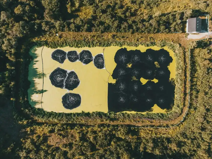
Thick scum caps and persistent foaming are abnormal, even when some surface material is normal on a secondary clarifier (per Top 5 Signs blog framing, 2025). Two distinct biological mechanisms drive secondary clarifier scum, and confusing them leads to misapplied fixes.
The first is Nocardia or Microthrix parvicella foaming — a brown, sticky, biological foam with high filament density. Trigger conditions are well known: low F/M ratio (long Solids Retention Time (SRT)), low DO, high residual fats and oils, and warm mixed liquor in the 15–25°C range. These are the same conditions that produce bulking sludge, so foam and bulking often appear together. Microscopic exam is the only reliable way to confirm — foam without filaments is rarely Nocardia.
The second is denitrification floatables — brown, odorous material that rises in clumps from the sludge blanket when nitrate-rich mixed liquor enters the secondary clarifier and denitrifies in the blanket. The fix is process control, not skimmer adjustment: raise the RAS rate to 50–100% of influent flow, add an anoxic zone upstream to denitrify before clarification, or reduce aeration intensity to lower effluent nitrate. Target DO in the aeration basin at 1.5–2.5 mg/L and conventional activated-sludge SRT at 5–10 days.
For longer-term control of filamentous foaming, operators are increasingly pairing manual foam control with sludge age control automation to keep SRT in a tighter band and avoid the low-F/M conditions that select for Nocardia.
Step-by-Step Clarifier Scum Diagnostic Flow
Run this decision tree in 30–60 minutes to identify the active root cause before changing any setpoint.
- Step 1 — Classify the scum. Run the texture + color + odor test from the opening table. Assign the event to one of three families: FOG, hydraulic, mechanical, or biological. Do not skip this step — every subsequent action depends on the family assignment.
- Step 2 — If FOG is suspected: pull a sample for laboratory FOG analysis in preservative glass containers and audit upstream grease sources within 24 hours. Check grease trap pump-out logs and look for new commercial contributors.
- Step 3 — If hydraulic is suspected: survey weir plate levels with a surveyor's level, calculate the actual SOR and weir loading rate against the 1.2–2.0 m/h and <250 m³/m·d targets, and inspect inlet baffles for damage or missing panels.
- Step 4 — If mechanical is suspected: walk down the clarifier under confined-space entry protocols and measure skimmer blade tip height and scum baffle submergence against the targets in the previous section. Photograph and log the readings.
- Step 5 — If biological is suspected: pull a mixed liquor sample for Sludge Volume Index (SVI), microscopic filament exam, and DO/nitrate profile upstream of the secondary clarifier. Compare against DO 1.5–2.5 mg/L and SRT 5–10 days.
If two root-cause families are active (for example, FOG plus denitrification floatables after a high-rainfall event), address the FOG source first because it will keep re-loading the secondary clarifier regardless of process control changes downstream.
Prevention Plan: Daily, Weekly, and Monthly Tasks

Convert the diagnostic into a recurring routine so the same scum event does not reappear in 3–6 months. The cadence below assumes a single-shift operator presence; for unmanned plants, multiply the weekly intervals accordingly.
| Frequency | Task | Pass/Fail Threshold |
|---|---|---|
| Daily | Visual scum layer thickness at scum beach; weir inspection; RAS rate verification | Scum layer <25 mm; no grease clumps on weir; RAS within 50–100% of Q |
| Weekly | Skimmer rotation test; scum box volume measurement; upstream source audit | One full revolution per 20–30 min; scum box emptied on schedule; no new high-FOG contributors |
| Monthly | Weir plate level survey; skimmer blade and baffle corrosion inspection; settleable solids in/out and sludge blanket depth log | Weir tolerance <3 mm; no visible corrosion pitting; blanket within design depth |
| Quarterly | Full skimmer mechanism inspection; scum beach cleaning; structural corrosion assessment; predictive maintenance review | All setpoints within tolerance; no deferred maintenance items; for plants scaling this cadence, see predictive maintenance for wastewater treatment plants |
Settleable solids in/out of the clarifier, sludge moisture content, sludge pumping cycle, and sludge blanket depth are the four parameters to log every shift because they are the leading indicators of an emerging scum event (per Primary Clarifiers monitoring guidance, 2024). A rising sludge blanket with falling settleable solids removal is the classic signature of an incipient denitrification event 24–48 hours before the scum shows on the surface.
Frequently Asked Questions
What is the most common cause of heavy scum on a primary clarifier? FOG ingress from upstream commercial or residential sources is the most common cause, producing greasy, dark, oily material that accumulates within hours of a hydraulic upset. Confirm with a certified lab FOG test in preservative glass containers, then audit upstream grease traps and loading.
How do I tell the difference between FOG scum and biological foam? FOG scum is heavy, greasy, and smears between gloved fingers; biological foam is light, fluffy, and often brown, with visible filaments under the microscope. FOG dominates on primary clarifiers; biological foam dominates on secondary clarifiers and follows low F/M and low DO conditions.
What surface overflow rate should a primary clarifier run at? Standard design practice targets 1.2–2.0 m/h at average flow for primary clarifiers. Above 2.0 m/h, surface velocity exceeds what the skimmer mechanism can capture, and scum is pushed past the beach regardless of skimmer setpoint.
Why is brown odorous scum rising from the sludge blanket in my secondary clarifier? That is denitrification floatables — nitrate in the mixed liquor is denitrifying inside the sludge blanket, and the nitrogen gas lifts sludge clumps to the surface. Raise the RAS rate to 50–100% of influent flow, add an anoxic zone upstream, or reduce aeration intensity to cut effluent nitrate before the secondary clarifier.
Can a DAF unit upstream of the clarifier reduce scum? Yes. A well-sized DAF system upstream of the primary clarifier typically removes 60–90% of FOG and suspended solids, which collapses the scum layer to a manageable 2–5 mm and protects downstream biological treatment. For plants with chronic FOG loading, this is the most reliable control point — see the HydropureWater DAF system specification for sizing against your peak FOG load.