What Is a Moving Bed Biofilm Reactor and Why It Matters in 2026
Moving bed biofilm reactor design centers on free-floating plastic carriers filled to 30-70% of reactor volume. Coarse-bubble aeration or mixers keep carriers moving; outlet sieves retain media without sludge recirculation. Design HRT is typically 4-8 h for carbonaceous removal and 6-12 h for nitrification at 10-12 °C.
A Moving Bed Biofilm Reactor (MBBR) grows biomass on those carriers and retains them with perforated-plate or cylindrical sieves on the outlet. Washout of attached biomass is structurally impossible at steady state. The process was developed in Norway in the late 1980s and commercialized by Kaldnes (now Veolia AnoxKaldnes), which remains the dominant installed-base brand globally (per the top-ranked AnoxKaldnes product listing on DirectIndustry, 2026).
Three engineering facts justify MBBR selection in a 2026 design review. First, the global MBBR market exceeded USD 3.4 billion in 2025 and is forecast at 7-9% CAGR through 2030 per recent industry outlooks — the technology is mature, not experimental. Second, attached biomass of 3,000-6,000 mg/L on the carrier surface sits roughly 50-100% higher than the 2,000-4,000 mg/L MLSS typical of conventional activated sludge. That is why MBBR reactors run at 4-15 g COD/m²·d versus 0.3-0.6 kg COD/kg MLSS·d for CAS at comparable volume. Third, fixed biomass removes suspended-growth bulking risk — a practical point when industrial operators have limited process staff. Tightening effluent limits in China, the EU, and the US push EPCs toward attached-growth trains that hit ammonia targets at low temperature in a smaller footprint than CAS.
The Four-Step MBBR Process Flow
An MBBR train is conceptually simple, but each upstream and downstream unit decides whether the biofilm stays healthy. Walk the four steps in order. For a stage-by-stage drawing with design values, see our MBBR process flow diagram guide.
Step 1 — Influent screening and equalization. Mechanical bar screens with 1-3 mm openings protect carriers from ragging and fibrous wrap. Flow equalization damps COD and TKN peaks that would otherwise shock the biofilm. Size the equalization basin at 6-12 hours of average flow for industrial streams. The GX Series rotary bar screen for MBBR headworks is sized to this duty band.
Step 2 — Pre-treatment. Dissolved air flotation (DAF) or a primary clarifier removes FOG, TSS, and colloidal matter. Design the MBBR for influent TSS <200 mg/L — higher solids foul the carrier surface and cut effective area within 2-4 weeks. A HydropureWater DAF system for MBBR pre-treatment typically cuts TSS from 400-800 mg/L down to 50-120 mg/L in a single stage on food and dairy effluent.
Step 3 — MBBR biological stage. Carriers fluidize under fine-bubble aeration through EPDM disc diffusers on the floor. Dissolved oxygen setpoint is 2-4 mg/L aerobic and 0.2-0.5 mg/L anoxic. Air supplies O₂ and mixing together. For anoxic or anaerobic stages, slow-speed mechanical mixers (typically 30-60 rpm, 4-8 W/m³) keep carriers suspended without aeration.
Step 4 — Carrier retention and post-treatment. Perforated-plate or cylindrical wedge-wire sieves with slot size 7-10 mm larger than the carrier's largest dimension retain media while clarified effluent passes downstream — usually a lamella clarifier, MBR, or disinfection contact basin. Sieve headloss is typically 50-150 mm at design flow and must sit in the hydraulic profile.
Carrier Media Selection: K1, K3, Biochip, and Engineered Variants
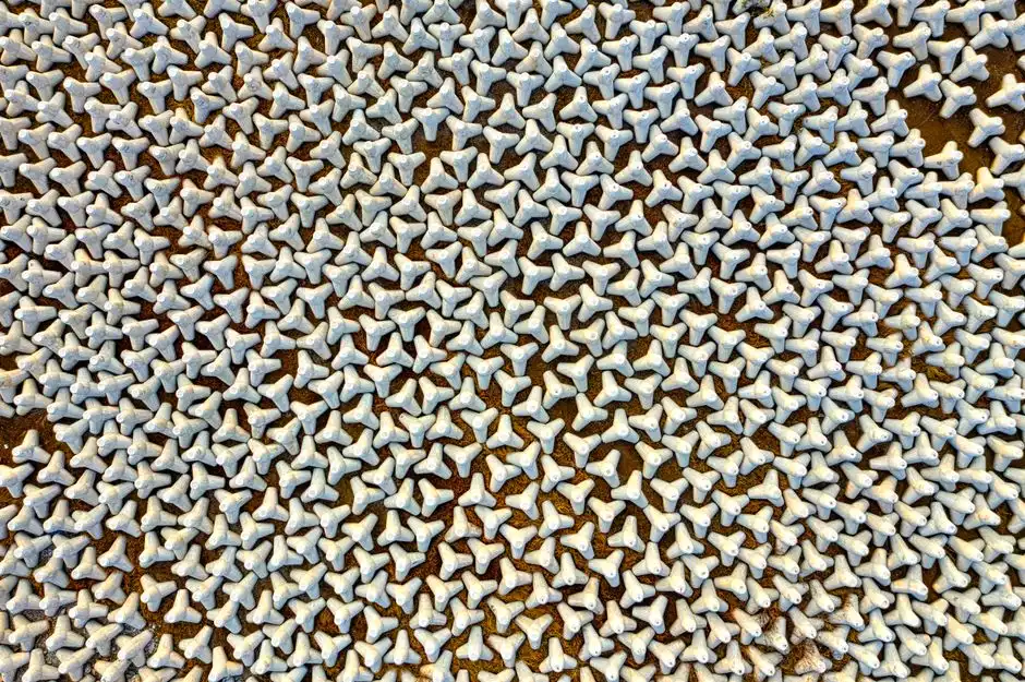
Carrier selection drives 70-80% of MBBR performance. The four commercial families an EPC will encounter differ in specific surface area, density, cost, and colonization behavior — never pick by habit.
| Carrier family | Geometry / material | Specific surface area (m²/m³) | Density (g/cm³) | 2026 price band (USD/m³) | Best-fit wastewater |
|---|---|---|---|---|---|
| K1 | Cylindrical HDPE, 10 mm dia. | ~500 | 0.95-0.98 | $80-120 | Municipal, low-to-mid COD |
| K3 | High-cylinder HDPE, 25 mm | 600-800 | 0.96-0.98 | $120-180 | Industrial, high COD, landfill leachate |
| Sponge / foam | Polyurethane cubes, 20-30 mm | 1,200-3,000 | 0.95-1.05 (wet) | $250-350 | Toxic / recalcitrant streams, decentralized |
| Engineered biochips (e.g. Mutag) | Porous sintered glass / ceramic, 10-15 mm | 1,500-2,500 | 1.05-1.20 | $300-400 | Pharma, landfill leachate, high ammonia |
Selection rule of thumb used in current practice: high-strength industrial streams (COD >2,000 mg/L) and landfill leachate benefit from protected inner-surface carriers like K3 or sponge variants. Shielded area limits abrasion loss of biofilm under high organic load. Municipal and low-strength industrial (COD <800 mg/L) is dominated by K1 because lower-cost media still deliver 70-90% COD removal at HRT 4-8 hours. Carrier diameter also governs fluidization air demand. A 25 mm K3 cylinder fluidizes at lower air flux per tank area than a 10 mm K1. K1 still delivers more surface area per cubic meter of reactor — that tradeoff sets blower size.
Moving Bed Biofilm Reactor Design Parameters and Sizing
Moving bed biofilm reactor design fixes four inputs first: influent flow Q (m³/d), influent COD or BOD load (kg/d), target effluent quality, and winter design temperature. Reactor volume then follows from carrier specific surface area and the chosen surface loading rate.
| Parameter | Typical design range | Notes |
|---|---|---|
| Fill fraction (carrier volume / reactor volume) | 30-70%, most designs 40-60% | Higher fill → smaller reactor, higher air demand |
| HRT, aerobic carbonaceous removal | 4-8 h | Below 3 h risks incomplete COD oxidation |
| HRT, nitrification stage | 6-12 h | At 10-12 °C winter design |
| Organic surface loading | 4-15 g COD/m²·d | Lower for high-strength / toxic streams |
| Ammonia surface loading | 0.5-2.0 g NH₃-N/m²·d | Derate for temperature below 15 °C |
| Dissolved O₂ (aerobic) | 2-4 mg/L | 4-6 mg/L for high-rate BOD removal |
| Specific oxygen demand | 0.8-1.2 kg O₂/kg BOD removed | Plus 4.6 kg O₂/kg NH₃-N nitrified |
| Temperature derating, nitrification | ~3-5% loss per °C below 15 °C | Design winter at 10-12 °C for temperate climates |
Worked sizing example. Municipal plant, Q = 500 m³/d, influent COD = 400 mg/L, target effluent COD = 50 mg/L. Substrate to remove: 500 × (0.400 - 0.050) = 175 kg COD/d. Choose K3 carrier at 800 m²/m³ specific surface area and organic loading 8 g COD/m²·d (mid-range, conservative for municipal). Required carrier surface area = 175 kg/d ÷ 0.008 kg/m²·d = 21,875 m². Reactor volume of carriers = 21,875 ÷ 800 = 27.3 m³. At 40% fill fraction, total reactor volume = 27.3 ÷ 0.40 = ~68 m³. HRT = 68 × 24 / 500 = 3.3 h — below the 4-8 h comfort band for single-stage carbonaceous removal, so a 2-stage aerobic train is the practical answer. Most plants we size for municipal duty end up with two or more reactors in series rather than one large tank for this reason.
Aeration design follows directly. For 175 kg COD/d removed, oxygen demand at 1.0 kg O₂/kg COD is ~175 kg O₂/d. Fine-bubble EPDM disc diffusers (typically 9-12 mm) on a floor grid supply that load at 20-25% clean-water transfer efficiency, derated 30-50% for process conditions.
How Does MBBR Cost Compare with Activated Sludge?
MBBR capital cost for industrial plants in the 50-500 m³/d band typically lands at $450-650 per m³/d of capacity, with OPEX at $0.12-0.22 per m³ treated at current steel, EPDM, and blower prices. Conventional activated sludge often needs more tank volume for the same ammonia duty and carries bulking risk that MBBR avoids because biomass stays on carriers.
Energy still dominates operating cost. Aeration is 60-70% of MBBR energy use. Versus CAS at comparable load, MBBR usually wins on footprint and startup time, while CAS can win on very large municipal civil packages where economies of scale flatten unit CAPEX. For stainless steel process skid pricing, material grade, seismic and wind loadings, automation level (PLC vs SCADA), and diffuser type each swing the quote by about ±20%.
High-COD esterification wastewater is a different first-pass choice. Anaerobic digestion often precedes aerobic polishing there; use the parameters for upflow anaerobic sludge blanket uasb reactor for esterification process waste water treatment when the duty is anaerobic COD cutting rather than aerobic biofilm nitrification.
MBBR vs IFAS, MBR, and SBR: 2026 Technology Comparison
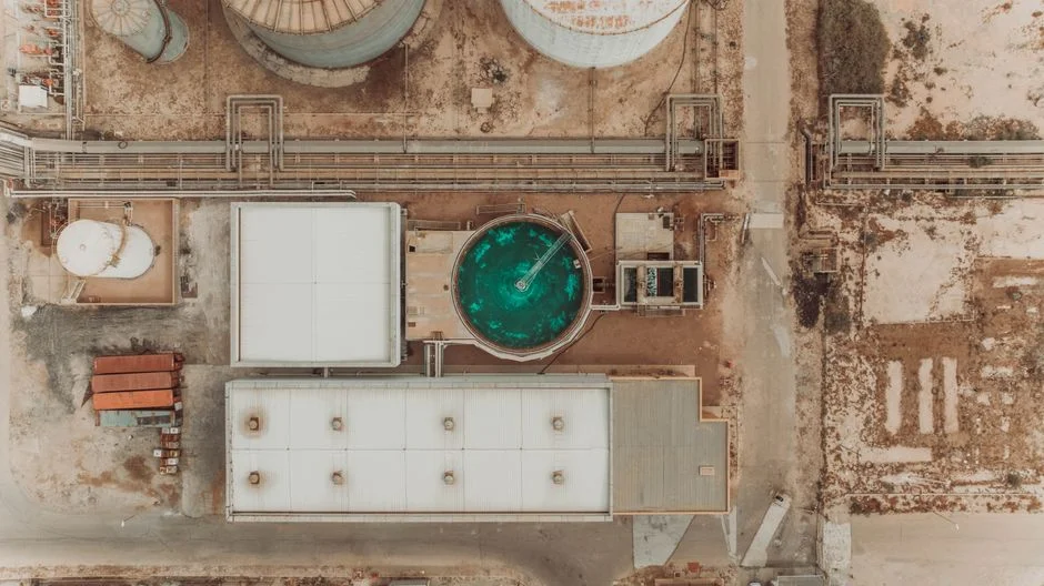
An EPC will frame MBBR against three alternatives. The matrix below is what you put on the decision slide when procurement asks why not IFAS or MBR.
| Criterion | MBBR | IFAS | MBR | SBR |
|---|---|---|---|---|
| Typical effluent COD (mg/L) | 50-125 | 40-100 | <30 | 40-100 |
| Effluent TSS (mg/L) | 20-80 (post-clarifier) | 15-50 | <1 (turbidity) | 15-40 |
| Ammonia removal efficiency | 80-95% (nitrification stage) | 90-98% | 95-99% | 85-95% |
| Footprint relative to MBBR | 1.0× | 0.7-0.9× | 0.5-0.7× | 1.2-1.5× |
| CAPEX vs MBBR | 1.0× | 1.2-1.35× | 1.8-2.5× | 0.8-1.0× |
| OPEX band (USD/m³) | $0.08-0.22 | $0.10-0.28 | $0.18-0.45 (membrane replacement $0.10-0.20/m³) | $0.10-0.25 |
| Sludge yield | Low (attached growth) | Moderate (hybrid) | Low (long SRT) | Moderate |
| Operator skill required | Low-medium | Medium | High (membranes) | Medium-high (sequencing) |
| Best fit | Industrial >200 m³/d, retrofit of CAS basins | Cold-climate nitrification, CAS retrofits | Water reuse, tight space, pharma/electronics | Small flows, batch discharge, intermittent operation |
The MBBR vs IFAS question turns on temperature. IFAS, the hybrid that suspends carriers inside an activated-sludge basin, delivers 5-10% better nitrification at 8-12 °C because biofilm and suspended biomass work in series. CAPEX is 20-35% higher — see the IFAS working principle explained in our 2026 design guide and the 2026 IFAS maintenance cost breakdown for the OPEX side ($0.04-0.18/m³ for IFAS carrier-related maintenance). MBBR vs MBR is a reuse question: MBBR effluent fits discharge to surface water or further biological polishing; MBR fits reuse-quality water or sub-1 μm solids. MBBR-MBR trains are increasingly common for industrial reuse. An integrated MBR polishing downstream of MBBR cuts membrane footprint by 30-40% versus standalone MBR because MBBR takes most of the BOD load off the membrane. MBBR vs SBR: SBR is batch-operated with simpler controls but needs equalization volume and skilled sequencing; MBBR is preferred for continuous industrial flows above 200 m³/d.
How Do You Select a Clarifier After MBBR?
Clarifier selection after an MBBR reactor starts from effluent TSS targets and sludge settling behavior, not from habit. Post-MBBR solids typically land at 20-80 mg/L after a well-sized secondary clarifier; if the discharge permit needs lower TSS or the plant feeds membranes, raise the solids capture duty accordingly.
Primary clarification or DAF belongs upstream when influent TSS exceeds about 200 mg/L, because high solids foul carriers within 2-4 weeks. Secondary options after the biofilm stage include rectangular or circular clarifiers and lamella packs. Lamella units cut footprint when site area is tight and solids settle reasonably. For industrial trains that need compact polishing, a lamella clarifier for MBBR effluent solids capture is the usual choice before disinfection. Energy and sludge handling then decide the rest: sludge yield from MBBR is low relative to CAS, so underflow pumping and thickening can stay modest if the hydraulic profile already includes 50-150 mm sieve headloss.
2026 Compliance Targets: Effluent Quality the Design Must Hit
Design without regulatory numbers is academic. The 2026 discharge limits an MBBR specification must clear in the three largest markets are listed below.
| Region / standard | COD (mg/L) | BOD (mg/L) | NH₃-N (mg/L) | TN (mg/L) | TP (mg/L) | Source |
|---|---|---|---|---|---|---|
| China GB 18918-2002 Grade 1A (2024-2025 updates) | ≤50 | ≤10 | ≤5 (8) | ≤15 | ≤0.5 | China MEE |
| EU UWWTD 91/271/EEC (10,000-100,000 PE) | ≤125 | ≤25 | — | ≤15 | ≤2 | European Council, 2024 review pending |
| US EPA secondary treatment (40 CFR 133) | — | ≤30 (30-day avg) | — | — | — | 40 CFR Part 133 |
A single aerobic MBBR stage hits carbonaceous targets comfortably on mid-strength effluent (70-90% COD removal, 80-95% ammonia removal under warm conditions). Full China 1A TN and TP compliance almost always needs a downstream anoxic MBBR zone with 200-400% mixed-liquor recycle. Add chemical P precipitation with FeCl₃ or alum at 1.5-2.5 mol Fe/mol P. Reference the 2026 chemical wastewater discharge standard compliance guide for the full global table.
2026 CAPEX and OPEX Benchmarks for MBBR Plants
Procurement will not accept a vague range. The 2026 numbers below are the bands a turnkey MBBR plant falls into at current steel, EPDM, and blower prices.
| Plant scale | CAPEX band (USD per m³/d capacity) | OPEX band (USD per m³ treated) | Notes |
|---|---|---|---|
| Industrial 50-500 m³/d | $450-650 | $0.12-0.22 | Package / skid-mounted, epoxy-coated carbon steel |
| Industrial 500-5,000 m³/d | $250-450 | $0.08-0.15 | Civil tanks + fine-bubble grid, concrete basin option |
| Municipal >10,000 m³/d | $150-300 | $0.06-0.10 | Concrete aeration tanks, large blower rooms |
| Modular / packaged (sub-50 m³/d) | $500-800 | $0.15-0.25 | Containerized, factory-tested |
OPEX is dominated by aeration, which is 60-70% of energy use. Cost drivers that swing these bands by ±20% include stainless vs epoxy-coated carbon steel tanks, fine-bubble vs coarse-bubble diffuser type, automation level (PLC vs SCADA), and seismic or wind loadings on outdoor basins. For sub-50 m³/d low-strength applications the Underground Package Sewage Treatment Plant (WSZ Series) runs as a packaged MBBR variant and avoids the civil cost line entirely. See the broader 2026 municipal sewage treatment plant price benchmarks for the full range across CAS, SBR, MBBR, and MBR.
Selection checklist before locking the P&ID:
- Confirm winter temperature and ammonia surface loading (derate below 15 °C).
- Fix fill fraction in the 40-60% band unless air demand or footprint forces otherwise.
- Keep influent TSS <200 mg/L with DAF or primary clarification.
- Size sieves for 50-150 mm headloss at design flow.
- Choose post-treatment (lamella, MBR, or disinfection) from the permit TSS and reuse targets.
- Compare stainless skid vs coated steel against local corrosion and seismic codes.
- Budget blower energy as 60-70% of OPEX and stress-test DO at 2-4 mg/L aerobic.
Integration with Pretreatment and Polishing: Building a 2026 Hybrid Train
MBBR almost never runs alone in 2026. The three hybrid trains that show up most often in industrial and municipal specs are below.
- Food & beverage (mid-strength): Bar screen → equalization → DAF → MBBR (2-stage aerobic) → lamella clarifier → ClO₂ generator for final disinfection. Typical influent COD 1,500-4,000 mg/L, effluent COD <100 mg/L.
- Landfill leachate (high-strength, recalcitrant): Equalization → MBBR (K3 or sponge) → MBR → RO. MBBR takes 60-70% of the COD load off the membrane stage, dropping membrane replacement frequency from 18 to 30+ months.
- Ammonia-rich industrial (poultry, fertilizer side-streams): MBBR (anoxic, methanol or glycerol dosing) + MBBR (aerobic, nitrification) + MBBR (aerobic, post-polish). Three-stage biofilm train is more compact than equivalent CAS/IFAS at the same ammonia load.
For polishing after MBBR, the 2026 ozone oxidation guide covers how O₃ cuts residual COD and color. The high-turbidity wastewater treatment solution guide covers hot TSS on the influent side. Bookmark both before locking the P&ID.
Who This Is For and Next Step
MBBR buyers who benefit most are plant engineers, EPC process leads, and procurement managers sizing industrial or municipal trains above about 50 m³/d, or retrofitting carriers into existing aeration basins. Look elsewhere if the duty is pure batch discharge without continuous flow. Also look elsewhere if the permit already forces reuse-quality effluent that needs standalone MBR or RO without a biological roughing stage.
When influent COD, TKN, winter temperature, and a discharge target are already known, send those four numbers with your flow sheet for a carrier fill and aeration check. Request a sizing review through our MBBR design inquiry form.
Frequently Asked Questions
What fill fraction should an MBBR be designed to in 2026?
Most current designs run 40-60% carrier fill by reactor volume. Below 30% the surface area is underutilized. Above 70% the air demand to keep carriers fluidized rises sharply and biofilm sloughing increases, so stay inside the mid band unless footprint forces a higher fill with larger blowers.
How long does MBBR take to start up compared with activated sludge?
A new MBBR reaches design ammonia removal in 2-4 weeks at 18-25 °C because the carriers retain biomass. There is no requirement to build mixed liquor from scratch, which cuts startup by 30-50% versus conventional activated sludge under the same temperature and load.
Can MBBR be retrofitted into an existing activated-sludge basin?
Yes, and it is the most common 2026 retrofit use case. Adding carriers at 20-30% fill to an aeration tank typically doubles the nitrification capacity without new tankage. IFAS is the alternative and is detailed in the IFAS working principle 2026 design guide.
What is the largest MBBR plant operating in 2026?
Veolia AnoxKaldnes has multiple municipal MBBR installations above 200,000 PE in Europe. Municipal plants larger than 50,000 m³/d are now standard references for new municipal tenders in Northern Europe and the Yangtze delta, and EPCs commonly cite those scales when proving continuous biofilm trains for large cities.
What stainless steel process skid cost factors matter most?
Stainless grade, tank wall thickness for seismic and wind loads, fine-bubble versus coarse-bubble diffuser grids, and PLC versus SCADA automation each move skid CAPEX by roughly ±20%. For sub-50 m³/d packaged duty, epoxy-coated carbon steel often undercuts stainless unless the site has aggressive chloride or outdoor corrosion exposure.