Why IFAS Exists: The Retrofit Problem Every Plant Hits by 2026
IFAS working principle for industrial wastewater retrofit is one sentence: free-floating biofilm carriers inside the existing aeration tank anchor slow-growing nitrifiers, cutting effluent ammonia below 2 mg/L without adding basin volume, while suspended MLSS keeps removing BOD and the plant keeps its clarifiers.
Three pressures converge on BOD- and nitrification-limited municipal and industrial plants in 2026. Typical permits now fall in the 1.0–5.0 mg/L NH₃-N range across EU, China, and US jurisdictions. Tank volumes are capped inside existing battery limits. Load volatility from industrial sidestreams keeps growing beyond what conventional activated sludge (CAS) can buffer.
The bottleneck is biological. Nitrifiers grow slowly (μmax ≈ 0.33 d⁻¹ at 20 °C), so they wash out at solids retention times (SRT) below roughly 8–10 days. Raising mixed-liquor SRT to protect them usually means bigger basins or higher MLSS, and both are expensive. In the EU the compliance clock is running: according to the European Commission, the revised Urban Wastewater Treatment Directive entered into force on 1 January 2025, moving nutrient-removal duties from directive text toward national permits.
Integrated Fixed-Film Activated Sludge (IFAS) breaks that trade-off by anchoring nitrifiers to free-floating carrier media inside the existing aeration tank, decoupling biological SRT from hydraulic retention time (HRT). It is one of the few upgrades documented as a cost-saving path for capacity-constrained plants (per mbbr-media.com's IFAS explainer) because the aeration basin, blowers, and clarifiers are largely reused. The rest of this article answers the engineering question behind that pitch. How exactly does IFAS combine biofilm carriers with activated sludge to deliver >95% ammonia removal in a single tank, and what do the 2026 design numbers look like?
IFAS Working Principle for Industrial Wastewater Retrofit: Two Biomasses, One Tank
IFAS is a conventional activated-sludge aeration basin into which free-floating, biofilm-supporting carrier media have been added. Both biomasses — suspended mixed liquor and attached biofilm — stay biologically active in the same reactor at the same time. The mechanism unfolds in five linked steps.
- Soluble BOD/COD removal by suspended MLSS. Influent enters the aeration tank where mixed-liquor suspended solids (MLSS) at 2,500–4,000 mg/L adsorb and oxidize the bulk of soluble organics through the standard floc-based activated-sludge pathway.
- Carrier suspension and biofilm colonization. Polyethylene or polypropylene carriers — typically 10–50% volumetric fill, density 0.94–0.97 g/cm³ — are kept in motion by coarse-bubble diffused aeration. Biofilm 50–300 µm thick colonizes the protected internal surface, where shear is lower and sloughing is gentler than on the carrier exterior.
- Decoupled SRT for slow-growing nitrifiers. Autotrophic ammonia oxidizers (Nitrosomonas, Nitrobacter) attach to the biofilm and are retained indefinitely by perforated-plate or wedge-wire screens at the downstream end. Effective nitrifier SRT rises to 20–40+ days while mixed-liquor SRT stays at 10–25 days. That decoupling is the central engineering insight: nitrification proceeds at winter temperatures and short HRTs that would wash out a CAS system.
- Dual-purpose aeration. The same coarse-bubble grid that fluidizes the carriers transfers oxygen to both populations. Dissolved oxygen (DO) is controlled at 2.0–3.5 mg/L — low enough to limit stripping of young biofilm, high enough to keep nitrification unstarved. Air flux typically ≥ 25 m³/m²·h is required to maintain carrier motion across the full floor area.
- Clarifier separation with biofilm retention. Mixed liquor flows to a standard secondary clarifier; the suspended MLSS settles and returns as RAS, while biofilm stays attached to the carriers and is returned to the aeration tank. Sludge-wasting decisions therefore do not erode nitrifier mass, which is why IFAS achieves increased process stability under variable MLSS, SRT, and organic loading (per ssiaeration.com IFAS overview).
IFAS Process Flow, Step by Step
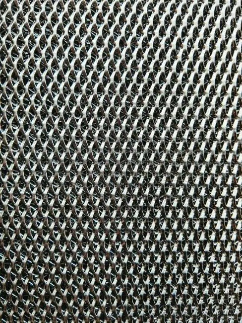
Most IFAS conversions we see follow the same six-stop flow sheet, and only two stops — media and retention screens — are equipment the CAS plant did not already own. One dewatering question reaches us every spring: ok for ifas media to be in an empty basin no flow? The dedicated process-flow guide answers it with drawdown limits and media-handling steps, so treat that page as chapter two of this one.
- Screening and primary clarification. Bar screens — typically a rotary mechanical bar screen at 3–6 mm aperture — and a primary clarifier protect downstream carriers from rag blinding and remove settleable TSS that would otherwise bury the biofilm.
- Anoxic zone (optional, for TN < 10 mg/L). Return liquor is mixed with influent under DO < 0.5 mg/L; carriers placed in this zone host denitrifying biofilm so total nitrogen can be pulled down without methanol dosing in many cases.
- Aeration basin with IFAS media. HRT 4–8 hr, MLSS 2,500–4,000 mg/L, carrier fill 10–50% (20–40% is the common design sweet spot). Coarse-bubble diffusers are sized for both oxygen transfer and carrier suspension; air flux ≥ 25 m³/m²·h is the minimum to prevent dead zones.
- Carrier retention screen. Wedge-wire or perforated plate with slot opening 5–10 mm smaller than carrier diameter; approach velocity 0.3–0.6 m/s prevents both clogging and carrier escape.
- Secondary clarifier. Surface overflow rate 18–25 m³/m²·d. IFAS sludge yield is roughly 20–30% lower than conventional AS (HydropureWater field data, 2026), which improves clarifier performance and reduces polymer demand.
- RAS / WAS control. Return activated sludge at 0.5–1.0 times the forward flow; waste activated sludge is drawn from the RAS line to hold MLSS at target. Biofilm mass is not removed by WAS — it stays on the carriers.
IFAS Design Parameters: MLSS, Carrier Fill and the Working Envelope
IFAS design parameters run at MLSS 2,500–4,000 mg/L and carrier fill 10–50% by volume, with the effective nitrifier SRT set by the biofilm instead of the WAS line. The numbers below are the working envelope a designer plugs into a mass balance. Where the published literature gives a range rather than a single value, the range is shown.
| Parameter | Typical IFAS design range | Notes |
|---|---|---|
| MLSS (aeration tank) | 2,500–4,000 mg/L | Lower than CAS (3,500–5,000) because biofilm carries part of the biomass |
| Carrier fill fraction | 10–50% volumetric (20–40% typical) | Above 50% risks fluidization problems |
| Specific surface area of media | 500–3,200 m²/m³ (PE carriers) | Higher area → smaller tank; trade-off is biofilm thickness control |
| Carrier density | 0.94–0.97 g/cm³ | Near-neutral buoyancy keeps carriers suspended without excessive air |
| HRT (aeration) | 4–8 hr | Shorter than CAS (6–10 hr) for the same load |
| Mixed-liquor SRT | 10–25 days | Controlled via WAS |
| Effective nitrifier SRT (biofilm) | 20–40+ days | Decoupled — set by biofilm retention, not WAS |
| DO setpoint | 2.0–3.5 mg/L | < 1.5 starves nitrification; > 4 wastes energy and strips biofilm |
| F:M ratio | 0.05–0.20 kg BOD/kg MLSS·d | Lower than CAS because biofilm adds effective biomass |
| Temperature window | 10–30 °C (rated) | Below 10 °C, halve ammonia loading or raise carrier fill to 40–50% |
| Ammonia surface loading on biofilm | 0.05–0.20 g NH₃-N/m²·d at 15–25 °C | Rate-limited below 10 °C |
| Backwash / carrier cleaning | Every 6–24 months in-situ aeration spike | Frequency is site-specific — operator logs, not a fixed schedule |
| Biofilm thickness (target) | 50–300 µm | Monitor monthly; > 400 µm risks sloughing events |
Two envelope limits deserve a field note. Wikipedia's MBBR reference records that carrier media can occupy as much as 70 percent of the tank in biofilm-only service, yet IFAS practice stops at 50% because the suspended MLSS still needs mixing and oxygen-transfer volume. Most plants we size for municipal and food-industry loads settle at 20–40% fill and never need the upper shelf.
How IFAS Biofilm Carrier SRT Drives Nitrification
IFAS biofilm carrier SRT sustains nitrification because attached autotrophs never leave with the waste-activated sludge stream. Wikipedia's summary of carrier-based reactors cites higher effective sludge retention time as the core advantage that makes nitrification favorable in biofilm systems, and IFAS quantifies it: 20–40+ days effective nitrifier SRT against 10–25 days for the mixed liquor. Designers exploit that gap by holding the mixed-liquor SRT short for denitrification-friendly sludge while the biofilm alone carries the ammonia load.
IFAS vs MBBR vs MBR vs Conventional Activated Sludge in the Aeration Tank
IFAS, MBBR, MBR, and conventional activated sludge answer the same aeration-tank question — hitting NH₃-N < 2 mg/L without pouring a new basin — with different biomass strategies and very different cost profiles. The choice is rarely about performance alone. The table below puts the options on the axes a procurement reviewer cares about.
| Process | Biomass | HRT (aeration) | Effluent NH₃-N | Footprint vs IFAS | CAPEX (relative) | OPEX (relative) | Best fit |
|---|---|---|---|---|---|---|---|
| IFAS | Hybrid: MLSS + biofilm carriers | 4–8 hr | < 1–2 mg/L | 1.0× | $$ | $ | Retrofit of existing AS basins, capacity-constrained plants |
| MBBR | Biofilm only, no return sludge | 3–6 hr | < 2–5 mg/L | ~1.0× | $$ | $ | New build or parallel train, variable load (see MBBR design guide for meat processing wastewater) |
| MBR | MLSS + submerged membrane | 6–10 hr | < 1 mg/L + TSS < 5 mg/L | 0.4–0.6× | $$$$ | $$$ | Water-reuse projects, sites with footprint constraint AND reuse need |
| Conventional AS | MLSS only | 6–10 hr | 5–15 mg/L (15–30 winter) | 1.2–1.5× | $ | $ | Baseline; usually fails 2026 NH₃-N limits without upgrade |
The IFAS upgrade advantage is concrete: 2–4× nitrification capacity in the same tank, with ~20–30% lower waste sludge than CAS (HydropureWater field data, 2026). For a 2026 reuse-scope project, the MBR membrane bioreactor still wins on effluent TSS, and teams comparing membrane routes should review the mbr working principle in detail before committing. For a BOD/nitrification retrofit on an existing basin, IFAS usually wins on CAPEX.
If a plant is also planning AI-driven process control, the IFAS configuration integrates cleanly with modern AI in wastewater treatment 2026 trends because the two-biomass system tolerates wider setpoint excursions than CAS. That tolerance is a useful buffer for machine-learning controllers still in commissioning. Retrofit scope and digital scope can therefore be phased onto the same basin without re-engineering either.
IFAS Media Retrofit for a Nitrification Upgrade: What Changes in the Tank
An IFAS media retrofit for a nitrification upgrade changes three physical items — carrier media, retention screens, and the air grid — and nothing about the clarifier or RAS pumping. The work is mostly mechanical, which is why outage windows stay short. A typical scope sequence looks like this:
- Confirm basin geometry and baffle layout against the target fill fraction — 20–40% first phase, 40–50% reserved for cold-climate service.
- Verify blower capacity for the higher coarse-bubble duty: ≥ 25 m³/m²·h floor flux with the carriers installed.
- Install wedge-wire or perforated-plate screens 5–10 mm undersize versus carrier diameter, with approach velocity 0.3–0.6 m/s.
- Charge media in one or two phases so nitrification recovers before the next fill increment.
- Sample biofilm thickness monthly against the 50–300 µm target and log DO alongside it.
- Rebalance diffusers to kill dead zones before blaming the media for poor fluidization.
Cold-climate plants should read the fill strategy twice. Below 10 °C the design answer is halving ammonia loading or raising carrier fill to 40–50%, not chasing MLSS. A retrofit staged this way keeps winter permit compliance on the biofilm alone, which is exactly the failure mode CAS plants hit every January.
IFAS Retrofit CAPEX in 2026: Ammonia Removal Economics and Payback
IFAS retrofit CAPEX in 2026 lands in the $1.5M–$8M band for a 20,000–50,000 m³/d facility, with a benchmark near $250–$650 per m³ of upgraded aeration volume (HydropureWater field data, 2026). The benchmark covers media plus screens plus a diffuser rebalance, and it moves with carrier fill, basin geometry, and blower headroom. OPEX moves differently: energy rises 5–15% to fluidize the carriers, but sludge handling falls 20–30%, so net OPEX lands roughly flat or slightly below the baseline AS it replaces.
Three payback drivers make the spend defensible to procurement:
- Avoided new-basin CAPEX. Retrofitting IFAS into an existing aeration tank saves 40–60% of the CAPEX that a parallel nitrification train would cost, because the tank, blowers, and clarifiers are reused.
- Avoided non-compliance penalties. 2026 NH₃-N limits under EU UWWTD revisions, China GB 18918-2002 amendment proposals, and US EPA nutrient strategies are tightening across all three jurisdictions. A single excursion event can dwarf a year of OPEX savings.
- Green-finance eligibility. Many 2026 funding windows — including EU cohesion funds and China pollution-control grants — explicitly favor retrofits over greenfield, narrowing the effective CAPEX gap further.
For plants also evaluating reuse, the broader 2026 water reuse outlook shows IFAS as a credible pre-treatment step in front of an MBR polish when reuse is the long-term target.
Common IFAS Operating Problems and How to Fix Them
Four failure modes cover most IFAS trouble tickets: winter nitrification loss, carrier carryover, biofilm sloughing, and poor fluidization — each with a known fix.
- Winter loss of nitrification. Cause: DO and temperature both drop; biofilm activity halves roughly every 7 °C. Fix: raise MLSS to the upper end of the 2,500–4,000 mg/L range, increase carrier fill to 40–50%, or add anoxic volume upstream to recover as TN instead of NH₃-N. A DCS upgrade can automate the seasonal setpoint shift — see the engineering buyer guide on DCS systems for sewage treatment in 2026.
- Carrier carryover into the clarifier. Cause: screen slot wear or wrong aperture, or approach velocity > 0.6 m/s. Fix: install a screen 5–10 mm undersize versus the carrier diameter and verify approach velocity with a flow survey.
- Biofilm sloughing events. Cause: toxic shock from a sidestream, or sustained F:M > 0.25. Fix: equalization upstream with online toxicity monitoring, and trim F:M back into the 0.05–0.20 range. Sloughing is not a failure — it is a control signal.
- Clogged carriers / poor fluidization. Cause: under-aeration or uneven diffuser layout. Fix: redistribute coarse-bubble diffusers to maintain > 25 m³/m²·h air flux across the full floor; check for biofilm thickness above the 50–300 µm target band as a routine monthly control check.
Deeper field detail is worth bookmarking before commissioning week. The IFAS Troubleshooting Guide 2026: Fix Media Loss, Foam & DO Failures works through screen failures and foaming events one symptom at a time, while the IFAS Common Problems and Solutions: 2026 Engineering Troubleshooting Guide collects the same fixes in case format.
Clarifier-side limits also matter in tight retrofits. Plants that pair the media conversion with plate settling can check the lamella clarifier working principle before fixing surface rates. The rest of the flowsheet stays untouched.
Who Should Specify IFAS — and Who Should Look Elsewhere
Specify IFAS when an existing aeration basin, tightening ammonia limits, and no room for new tanks define the project. Look elsewhere when there is no basin to begin with: for greenfield small industrial sites, the Underground Package Sewage Treatment Plant (WSZ Series) often reaches commissioning faster than a stick-built train. The IFAS working principle for industrial wastewater retrofit packages into three deliverables — carrier media, retention screens, and an airflow rebalance — so quotations concentrate on basin dimensions, influent load, and permit limits. Send those three inputs for a sizing review through the IFAS retrofit inquiry form.
Frequently Asked Questions
What does IFAS stand for and how does it work?
Integrated Fixed-Film Activated Sludge is the expansion. It combines free-floating biofilm carriers with conventional activated sludge in one aeration tank, with both biomasses active simultaneously. Typical performance: >95% NH₃-N removal at an effective nitrifier SRT of 20–40 days. The carriers are held by retention screens while settled MLSS recycles as return sludge, so the plant keeps its clarifier and RAS loop unchanged.
How is IFAS different from MBBR?
IFAS keeps a return-sludge activated-sludge process running alongside the biofilm, so the basin contains both MLSS and carriers. MBBR is biofilm-only — no return activated sludge, no clarifier-coupled MLSS control. IFAS is usually preferred for retrofits; MBBR is usually preferred for new parallel trains.
What carrier fill fraction is typical for IFAS?
10–50% volumetric, with 20–40% the common design sweet spot for municipal and industrial loads. Below 10%, nitrification capacity drops sharply. Above 50%, fluidization becomes difficult without disproportionate blower energy, which is why the working envelope stops there even though biofilm-only systems can run fuller.
Can IFAS be retrofitted into an existing activated-sludge basin?
Yes — that is its primary use case. The tank footprint, blowers, and clarifier are reused; the work scope is carrier media, retention screens, and diffuser rebalancing. Typical CAPEX savings versus building a new nitrification train: 40–60%. Outage windows stay short because the scope is mechanical rather than civil.
What effluent quality can IFAS achieve in 2026?
The typical envelope is BOD < 10 mg/L, COD < 50 mg/L, NH₃-N < 1–2 mg/L, and TN < 10 mg/L when an anoxic zone is included. Site-specific performance depends on temperature, load variability, and influent characterization. Pilot testing is recommended for any design pushing the lower bound of those numbers.