What IFAS Failure Looks Like on the Floor
IFAS failures cluster in media loss, surface foam, DO crashes, and biofilm sloughing. This IFAS media loss and effluent screen troubleshooting guide maps every alarm to a first-hour fix, holding DO at 3-4 mg/L and attached biomass at 5-15 g TSS/m².
Six alarms account for most after-hours calls from an IFAS basin. Media on walkways or in the launder means the retention screen is bleeding carrier. Foam rolling off the weir is a structural consequence of retaining free-floating media, not a surfactant upset.
Rising effluent NH3-N signals that nitrification has slipped, usually because the suspended-phase DO dropped below 3 mg/L or the aerobic SRT fell under 5 days. A high screen Δh reading is debris fouling or biofilm overgrowth on the bars. Low basin DO is the master alarm: it cascades into ammonia slip, foam intensification, and biofilm starvation. Visible clumps in the clarifier are biofilm sloughing, almost always from excessive mixing energy or a toxic slug.
The triage rule that prevents wasted hours: check the effluent screen and basin DO before anything else, because both symptoms feed every other failure mode. The Hazen & Sawyer full-scale IFAS demonstration at Greensboro confirmed that excessive screen headloss, once coupled with foaming, throttles the air supply to the basin. A "DO crash" with foam on the weir is therefore a hydraulics problem before it is an aeration problem (Hazen & Sawyer, IFAS demonstration report).
Hold these field-validated numbers before the diagnostic table: 3-4 mg/L DO in the suspended phase, 5-15 g TSS/m² attached biomass, and ~35% media fill for AnoxKaldnes K3 reference designs. Add an effluent screen with ~¼ inch openings backed by upstream bar screens under 6 mm. Every corrective action below returns the basin to one of those bands.
Carrier-based biological treatment is proven at scale — over 700 moving-bed biofilm systems are installed across more than 50 countries (Wikipedia) — but every one of them lives or dies by media retention. Design and carrier-selection background sits in the IFAS Working Principle: Process, Design & 2026 Industrial Data article. This page handles the alarms.
Symptom-to-Cause Diagnostic Table
Pick the row that matches what you see on the floor, then run the first-hour check before adjusting chemistry or media fill. The table links each symptom to a probable cause, the first parameter to verify, and a measurable acceptance criterion drawn from the Greensboro pilot and the MDPI IFAS operating-parameter review (MDPI, 2023-07).
| Symptom | Probable cause | First-hour check | Acceptance criterion |
|---|---|---|---|
| Media on walkway / launder | Effluent screen torn, undersized, or bypassed | Visual inspect screen bars, measure slot opening | ~¼ inch openings (Greensboro design) |
| Foam at weir | Natural foam trap from retained free-floating media | Verify spray nozzles on surface screen, check defoamant dose | Foam passes through ¼ inch bars, media retained |
| DO crash | Aeration throttled by foam on screen, or blower undercapacity | Read screen Δh, profile DO across basin length | 3-4 mg/L in suspended phase |
| Screen Δh rising | Debris loading, biofilm overgrowth, or upstream bypass | Pull a screen bar sample, inspect upstream bar screen | Upstream openings < 6 mm; Δh per OEM spec |
| Rising effluent NH3-N | DO < 3 mg/L, cold SRT < 5 days, or toxic slug | Log DO and temperature, check attached biomass on carrier | Attached biomass 5-15 g TSS/m² |
| Clarifier blanket rise / clumps | Excessive mixing energy or sudden DO swing | Reduce aeration intensity, inspect carrier for thin biofilm | Biofilm thin and uniform, not fluffy |
The upstream-screening rule (< 6 mm) is the prevention basis for the debris-loading row, and the ¼ inch effluent screen opening is the Greensboro-proven geometry for the media-loss row. If attached biomass is below 5 g TSS/m² the biofilm has been lost; if it is above 15 g TSS/m² the carrier is overloaded and sloughing will follow.
IFAS Operating Parameters and Attached Biomass Targets
Every troubleshooting step ends at a number. These are the bands an operator should benchmark against the SCADA before deciding whether a "fix" actually worked. The targets below combine the Greensboro pilot results with the MDPI review of IFAS operating parameters (MDPI, 2023-07). The Waqas et al. review (2023) describes IFAS as a hybrid process combining suspended and attached growth, and finds that longer HRT with appropriate SRT drives organic and nutrient removal.
| Parameter | Target band | Source / context |
|---|---|---|
| Suspended-phase DO | 3-4 mg/L | Greensboro pilot, required to keep biofilm fully aerobic |
| Total aerobic SRT | ~5.5 days at ~15 °C | Greensboro pilot, full nitrification held |
| Suspended-phase SRT | as low as 3.6 days | Greensboro pilot, when attached biomass carries nitrification |
| Media fill (K3 reference) | ~35% | Greensboro pilot, AnoxKaldnes K3 |
| Attached biomass | 5-15 g TSS/m² | Greensboro pilot, healthy operating window |
| Fixed-film fraction of total biomass | up to 50% | Greensboro pilot |
| Upstream bar screen opening | < 6 mm | Greensboro pilot, debris prevention |
| Effluent screen opening | ~¼ inch | Greensboro pilot, media retention with foam passage |
| Low-temperature nitrification | stable at 7-9 °C | MDPI review, Hopedale case |
One caution before anyone treats 35% fill as universal: the MDPI review documents fill ratios from 15% (polyester sponge, plug-flow pilot) to 60% (polyethylene carriers, OSPW treatment). HRT and SRT vary by an order of magnitude across the same studies. Match the target to the carrier, the wastewater, and the design HRT, not to a generic IFAS number.
In pure MBBR service, carrier fill can reach 70 percent of tank volume (Wikipedia), because a single-stage MBBR carries all of its biomass on the carriers. Retrofit IFAS fills stay far lower because mixing energy, not packing, limits the design. The cold-weather band of 7-9 °C at Hopedale held with low pollutant loading, so cold-weather stability is a function of holding the suspended-phase SRT logic, not a property of the media itself.
Fix #1 — IFAS Media Loss and Effluent Screen Troubleshooting
Media on the walkway is a screen problem until proven otherwise. Walk the perimeter first, then the screen itself. The retention principle is the same worldwide: a sieve keeps all the carriers in the tank to prevent the plastic carriers from escaping the aeration (Wikipedia).
Screen audit (10-15 minutes): Visually inspect every panel for torn bars, bent supports, and slot deformation. Measure the slot opening with a caliper or go/no-go gauge; if it exceeds ~¼ inch, the media has a path out. Check mounting rigidity and bottom support, because a screen that flexes under aeration pulses will let carrier through even at the correct slot size. Record the current Δh against the manufacturer spec; a value above spec with no visible foam points to debris fouling or biofilm overgrowth on the bars.
Cylindrical screen check: If Δh is elevated but the bars look clean, pull a dive or ROV inspection on cylindrical screens. Clogging at the bottom of the cylinder is a common silent failure that the surface Δh gauge will not localize.
Temporary measure: Lower aeration intensity to reduce media migration toward the screen face, then restore once the repair is complete. This buys time without starving the biology for more than a few hours. If the repair forces a basin drain-down, first confirm whether it is ok for ifas media to be in an empty basin no flow before pumping out.
Repair: Replace damaged screen panels with a slot size confirmed by the media vendor. Do not improvise a larger opening, and do not field-weld patches on perforated plate; the next media slug will find the gap. An upstream rotary mechanical bar screen at the headworks reduces the debris load that fouls the effluent screen in the first place.
Fix #2 — Foam Accumulation and Surface Management
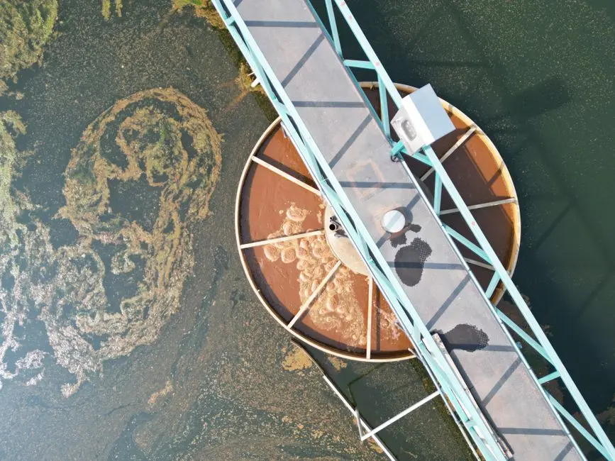
Foam in an IFAS basin is structural, not chemical. Free-floating media must be retained on the downstream side, so the surface of every IFAS cell behaves like a foam trap. Treating it as a surfactant upset leads to wasted defoamant and a screen that is still choking on foam.
The Greensboro team proved a mechanical workaround that any plant can copy. They mounted a vertical bar screen near the water surface with ¼ inch openings, supported at top and bottom, fitted with a spray nozzle directed at the bars, and slanted toward the direction of flow. The geometry passed foam while retaining media, and the spray kept the bars clear without operator intervention.
For the next high-load event, add a routine of temporary surface-foam wasting through a dedicated launder valve. This is the standard operator response when the surface screen is not yet installed. Use antifoam only as a supplemental measure, never as the primary control, because silicone and polymer defoamants accumulate on the carrier surface and depress attached biomass if overdosed.
Fix #3 — IFAS Basin DO Crash With Foam on Screen: Aeration Recovery
A DO crash in an IFAS basin is a hydraulics problem before it is an aeration problem. Foam on the effluent screen and elevated Δh together throttle the airflow to the basin, so adding blower capacity before clearing the screen just pushes more air against a higher backpressure.
First-hour sequence: Clear screen Δh and surface foam, then re-profile DO across the basin length. A healthy IFAS reads higher in the suspended phase than the biofilm consumes, because oxygen must diffuse through the biofilm layer to reach the nitrifiers attached to the carrier. If the profile is flat or low only at the effluent end, the cause is airflow throttling; if it is low at the inlet end, the cause is loading or mixing.
Mixing check: Verify that mixing energy is uniform enough to keep free-floating media in suspension. Channeling creates dead zones where biofilm starves even when the bulk DO reads 4 mg/L. A simple visual check of media distribution at the basin surface, or a TSS profile, will confirm.
Calibration note: Higher air flows relative to conventional activated sludge are normal in IFAS. Hazen & Sawyer observed no abnormal oxygen transfer efficiency at the Greensboro pilot despite higher than design airflow, so a high air reading is not, by itself, evidence of over-aeration. If a side-stream DAF pre-treatment unit is upstream, verify it is not returning a solids load that is driving biological oxygen demand beyond the design rate.
Fix #4 — IFAS Biofilm Sloughing, Clarifier Clumps, and Nitrification Slips
These three failures show up together because they share root causes. Excessive turbulence from over-aeration strips biofilm in sheets. A toxic slug load kills the inner biofilm layer, and the dead mass sloughs at the next air pulse. A debris-laden influent coats the first IFAS cell with floatables that smother carrier.
Sloughing response: Reduce mixing energy by trimming blower output or moving diffuser taps, then verify feed quality against the previous 24 hours. Pull carrier samples from each cell and weigh the attached biomass. Values below 5 g TSS/m² mean the biofilm has been lost and the system is running as a pure ASP, which it was not designed to do. Cold-weather nitrification at Hopedale held at 7-9 °C because the attached biomass carried the load, not the suspended MLSS (MDPI, 2023-07).
If clumps still reach the clarifier effluent during recovery, a polishing Multi-Media Filter for Water Treatment shields downstream reuse loops from TSS spikes while the biofilm rebuilds.
Debris response: Trace floatables in the first cell to recycled scum and influent screen bypass. Restore or upgrade upstream screening to openings finer than 6 mm, and check that the scum return line is not dumping grease and rags into the first cell. The Greensboro team flagged this as the single most underappreciated failure mode in retrofit IFAS projects.
Cold-weather SRT logic: When the aerobic SRT drifts below 5 days at low temperature, do not chase the suspended MLSS. Cut the suspended-phase SRT to ~3.6 days and let the attached biomass carry nitrification, exactly as the Greensboro pilot did at ~15 °C. Holding the total aerobic SRT near 5.5 days is what preserves the nitrification rate, not the suspended-phase number alone.
Before You Call the Media Supplier: A 7-Day Prevention Routine
If the diagnostic table sends you to the supplier before you have audited the screen, the DO, and the attached biomass, you are about to buy a fix for the wrong problem. Run this weekly routine first; it catches the failure modes above before they become 4 a.m. alarms.
Daily: Log basin DO at three points (inlet, mid, effluent), effluent screen Δh, and effluent NH3-N. A single point reading of DO is not enough to detect channeling in an IFAS basin.
Weekly: Pull carrier samples from each IFAS cell, dry and weigh the attached biomass, and compare against the 5-15 g TSS/m² band. Inspect the effluent screen and the upstream bar screen; verify upstream openings are still under 6 mm and that the spray nozzles on the surface screen are not plugged.
Monthly: Review the foam event log and spray-nozzle performance. Recalibrate defoamant dosing if used, and check that the dose rate has not crept above the level that begins to coat carrier surfaces.
Quarterly: Confirm the media fill fraction matches the design (35% for K3 reference designs) by volume displacement or drawdown test, and replace lost media in measured batches. A drop from 35% to 25% fill will silently cut nitrification capacity long before the operator notices it on the floor.
If media still collects on the walkway after this IFAS media loss and effluent screen troubleshooting sequence, request a formal screen and media review. Attach your Δh logs and carrier weights so the diagnosis starts from data.
Frequently Asked Questions
What dissolved oxygen target should I hold in an IFAS basin?
Hold 3-4 mg/L in the suspended phase across the basin length. The biofilm layer consumes oxygen before it reaches the nitrifiers attached to the carrier, so the bulk reading must stay high enough to push diffusion through the film. During recovery, log DO at inlet, mid-basin, and effluent points so channeling cannot hide behind a single reading.
How do I know if the attached biofilm is healthy?
Pull carrier samples weekly and weigh the attached biomass. The healthy window is 5-15 g TSS/m². Below 5 g TSS/m² the biofilm has been lost; above 15 g TSS/m² the carrier is overloaded and sloughing will follow within days. Compare cells against each other, because one thin cell usually marks a mixing dead zone rather than a basin-wide biofilm loss.
Why does my IFAS basin keep foaming even after I dose defoamant?
Foam is a structural consequence of retaining free-floating media. Treat it mechanically: install a slanted vertical bar screen with ~¼ inch openings and a spray nozzle, or waste surface foam through a dedicated launder during high-load events. Antifoam is a supplement, not the fix, and overdosing coats the carrier.
What upstream screen opening do I need to protect an IFAS basin?
Hold upstream bar screen openings under 6 mm, the smaller the better per the Greensboro pilot. Debris and scum bypass into the first IFAS cell is the most common silent cause of carrier fouling and high effluent screen Δh. Pair the fine screen with a spray header and weekly bar inspection to stop rags before they reach the carriers.
Can I drop the suspended-phase SRT in cold weather and still hold nitrification?
Yes. The Greensboro pilot held full nitrification at ~15 °C with a suspended-phase aerobic SRT as low as 3.6 days, provided the total aerobic SRT stayed near 5.5 days and the attached biomass carried the nitrification load. The MDPI review confirms stable cold-weather performance at 7-9 °C when these targets are held.
Why does IFAS ammonia slip follow low suspended DO?
Ammonia slip with low suspended DO means the biofilm is not receiving enough oxygen to carry nitrification. The bulk phase must read 3-4 mg/L because oxygen diffuses through the biofilm layer before reaching the attached nitrifiers. Check screen Δh and foam first — throttled airflow, not blower capacity, causes most low-DO events. Recover the profile before changing media fill or SRT.
How do I clear IFAS screen headloss from debris fouling?
Clear IFAS screen headloss by pulling a screen bar sample and inspecting the upstream bar screen for bypass. Debris fouling and biofilm overgrowth on the bars are the two usual causes; restore upstream openings under 6 mm and keep the spray nozzles clean. Verify Δh against the manufacturer spec after cleaning. If headloss returns within days, the source is scum return or influent screen bypass, not the effluent screen itself.