What "Membrane Aerated Biofilm Reactor" Actually Means
A Membrane Aerated Biofilm Reactor (MABR) is a wastewater treatment process in which a gas-permeable hollow-fiber membrane supplies bubble-less oxygen from the lumen to a biofilm attached on the outside of the fibers. Because oxygen diffuses inward while substrate in the bulk liquid diffuses outward into the biofilm, a stratified aerobic–anoxic biofilm forms on a single fiber, enabling simultaneous COD oxidation, nitrification, and denitrification in one reactor without a separate anoxic tank. The technology is also called Membrane Biofilm Reactor (MBfR) in the academic literature, with the concept traced to the work of Yeh and Jenkins in 1978 and consolidated in the MDPI 2023 review of MABR development (per Li et al., MDPI Water 15(3):436, 2023-01-22).
The single most common misconception — and the one that causes the most confusion in early project meetings — is that the membrane in MABR is a filter. It is not. The membrane is a gas-transfer device. Wastewater never crosses the membrane wall, there is no permeate, no reject stream, and no backwash cycle. Oxygen moves in one direction (lumen → biofilm) and pollutants diffuse inward from the bulk liquid to meet it. This is the exact opposite of an MBR membrane bioreactor system for reuse-quality polishing, where the membrane's job is to physically reject suspended solids from the mixed liquor.
Because oxygen is delivered without bubbles, off-gas stripping of volatile organics is suppressed, and oxygen utilization efficiency is far higher than in diffused-air systems — most of the O₂ that crosses the membrane is consumed by the biofilm before it ever reaches the bulk liquid. The physical form is a bundle of hydrophobic hollow fibers (typically PTFE, PP, PVDF, or composite) potted into a module and either submerged in an aeration tank or operated as a sidestream reactor with cross-flow along the fiber outer surface.
The MABR Working Principle: How Oxygen Reaches the Microbes
Pressurized air or pure O₂ is fed into the lumen of each hollow fiber. Oxygen permeates radially outward through the hydrophobic membrane wall by molecular diffusion. No bubbles form because the pores remain gas-filled and the water-intrusion pressure of the membrane is not exceeded — this is the engineering reason hydrophobic materials are specified, not a marketing preference. The driving force for transfer is the partial-pressure gradient between the lumen gas and the dissolved-oxygen concentration at the base of the biofilm, which sits at or near zero.
Reported oxygen transfer rates (OTR) for commercial MABR modules fall in the range of 5–15 g O₂/m²·day (process literature range, per MDPI 2023 review). That number is intentionally a range: it varies with lumen gas composition, lumen pressure, biofilm thickness, temperature, and substrate loading. Treat it as a screening figure for feasibility, not a guaranteed duty point.
Hydrophobicity of the membrane is what keeps liquid water out of the pores and sustains bubble-less transfer over multi-year operation. Once the pore surface is wetted — typically due to a pressure surge, surfactant shock, or fouling — the local OTR collapses and that fiber effectively goes dead until the module is chemically dried or replaced. This is why influent screening and surfactant control matter disproportionately in MABR design compared with diffused-air activated sludge.
The biofilm grows on the outer surface of the membrane, attached directly to the oxygen source. That orientation is the opposite of every conventional biofilter the reader has seen, where oxygen arrives last and substrate arrives first. In MABR, the highest dissolved-oxygen concentration in the entire system is at the membrane–biofilm interface, not in the bulk liquid.
Counter-Diffusion: Why the Biofilm Stratifies
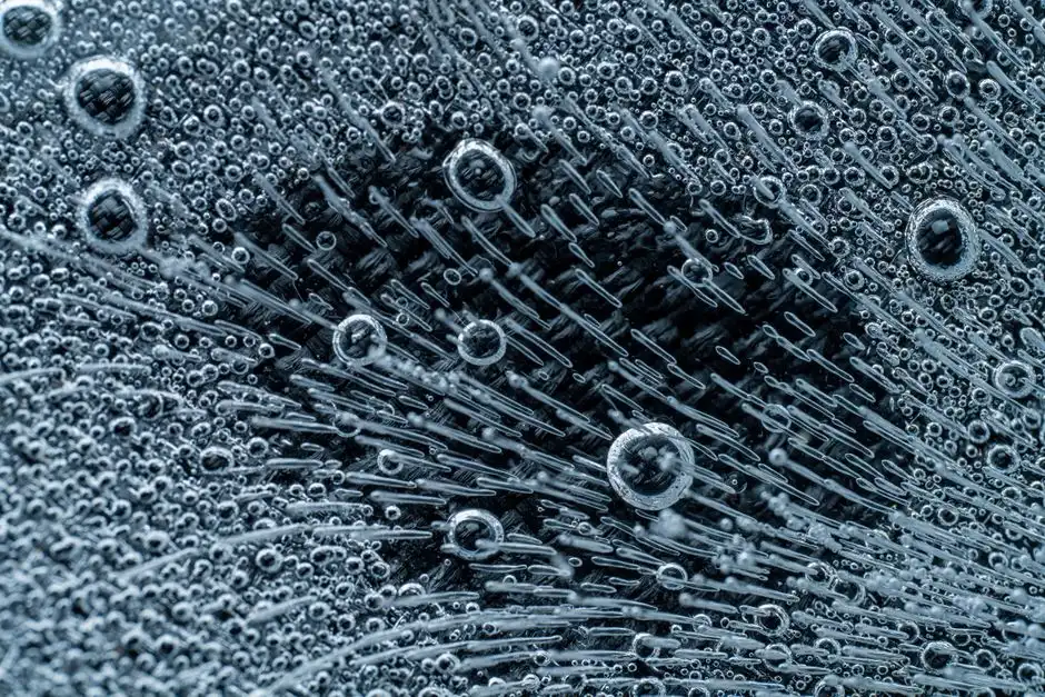
Counter-diffusion is the central physical insight of MABR. Two concentration gradients cross inside one biofilm: O₂ diffuses from the membrane outward toward the bulk liquid, while COD, NH₄-N, and other substrates diffuse from the bulk liquid inward toward the membrane. The two fluxes move in opposite directions. This is the opposite of co-diffusion in a conventional trickling filter or RBC, where O₂ and substrate both arrive at the outer biofilm face.
Because O₂ is consumed by heterotrophs and ammonia-oxidizing bacteria (AOB) near the outer aerobic band, an anoxic zone forms in the deeper biofilm close to the membrane. Reported biofilm thicknesses in the literature cluster in the 200–1,000 µm range (per MDPI 2023 review of biofilm morphology), and the operator's job is to keep thickness inside that band — too thin and the anoxic layer collapses, too thick and the aerobic layer starves and sloughs unpredictably.
The stratified layers, from the bulk liquid inward to the membrane, are:
- Aerobic outer band: high dissolved oxygen, near bulk-liquid COD, where heterotrophic oxidation and nitrification (AOB → NO₂⁻; NOB → NO₃⁻) proceed.
- Oxygen-depleted transition: DO falls to near zero as O₂ is consumed faster than it can diffuse in.
- Anoxic inner band: near the membrane, where denitrifying bacteria use the remaining COD or endogenous carbon to reduce NO₃⁻ to N₂. The membrane surface itself sees essentially no free O₂.
The practical consequence is simultaneous COD removal, nitrification, and denitrification in one biofilm on one fiber. There is no separate anoxic tank, no internal mixed-liqu recycle pump, and no methanol dosing for industrial streams that already carry enough biodegradable carbon. This is the single feature that, in the writer's experience on ammonia-rich industrial projects, decides whether MABR gets specified or ruled out.
Key Design and Operating Parameters
The table below consolidates typical design ranges a process engineer would put into a design basis memo. Values are drawn from the MDPI 2023 MABR review and conventional biofilm literature; project-specific numbers should always be confirmed by pilot testing.
| Parameter | Typical Range | Notes |
|---|---|---|
| Membrane material | PTFE, PP, PVDF, composite | Hydrophobic, water-intrusion pressure > operating lumen pressure |
| Oxygen transfer rate (OTR) | 5–15 g O₂/m²·day | Process literature range; varies with lumen gas and biofilm thickness |
| Biofilm thickness | 200–1,000 µm | Controlled by hydraulic shear and sloughing events |
| Organic loading rate (OLR) | 0.5–6 kg COD/m³·day | Higher than CAS per unit volume due to attached biomass density |
| Ammonia loading rate (ALR) | 0.2–1.5 kg NH₄-N/m³·day | Sidestream deammonification often runs at the upper end |
| HRT (sidestream) | 6–24 h | Mainstream retrofits can run shorter |
| SRT | Effectively infinite | Biomass is attached, not wasted with the effluent |
| COD removal | 70–95% | Depends on biodegradability and OTR |
| NH₄-N removal | 80–99% | Robust to cold temperatures due to retained nitrifiers |
| TN removal (single stage) | 50–80% | Up to >80% with Anammox-coupled sidestream |
SRT decoupling from HRT is the second-most-important concept on this page. Because biomass is attached, slow growers like nitrifiers (doubling time ~1–2 days at 10 °C) and Anammox bacteria (doubling time ~7–14 days) are retained automatically. This is why a MABR nitrifies reliably through winter at 6 °C while a parallel CAS basin loses its nitrification for two months.
Biofilm thickness is managed, not measured continuously in most plants. Operators use cross-flow velocity along the fibers and intermittent lumen-air ramping to shear excess biomass; a sloughing event is normal and resets the stratified layers. Pilot work is non-negotiable for any influent outside standard municipal range — high oil & grease, scaling cations (Ca²⁺, Ba²⁺), or fibrous solids can foul modules and are not always visible in jar tests.
MABR vs MBR vs Conventional Activated Sludge
This head-to-head is the section most often missing from the top-ranking MABR pages, and it is usually the table a consulting engineer actually wants before briefing a client. The short version: each technology wins in a different operating envelope, and the right choice is driven by effluent quality target, influent character, and footprint.
| Criterion | MABR | MBR | CAS |
|---|---|---|---|
| Membrane function | Gas transfer (no filtration) | Physical barrier (<1 µm pore) | No membrane |
| Biomass form | Attached biofilm on fibers | Suspended MLSS 8–12 g/L | Suspended MLSS 2–4 g/L |
| SRT | Effectively infinite | 15–30 d (with wastage control) | 5–25 d |
| HRT vs SRT | Decoupled | Partially decoupled by wasting | Coupled |
| Aeration energy for NH₄-N load | Lowest (high OUE) | High (fine-bubble diffusers) | High; 30–60% more than MABR for same NH₄-N load |
| Effluent TSS | 5–30 mg/L | <1–5 mg/L (reuse quality) | 10–30 mg/L |
| Reuse suitability | Needs polishing (DAF, sand filter, RO) | Direct to RO or disinfection | Needs tertiary filtration |
| Footprint | Smallest (high biomass density) | Moderate (membrane tank added) | Largest (long HRT) |
| Cold-weather nitrification | Robust | Robust if SRT held | Seasonal failure risk <10 °C |
| Toxic-shock tolerance | High (biomass retained) | Moderate (sludge wasting) | Low (washout risk) |
| Reject / waste stream | None | None from membrane (wasted sludge only) | Wasted sludge |
| Capex per m³/d (typical, mid-scale) | Moderate | Highest (membrane replacement) | Lowest |
When to choose which, in one line: pick MABR when the stream is high-ammonia, refractory, or footprint-constrained; pick MBR when reuse-quality permeate is the driver and a downstream RO train is the project bottleneck; pick CAS when influent is biodegradable municipal sewage at moderate strength and capital cost is the binding constraint. For projects where the influent swings between industrial and municipal character, an industrial wastewater treatment process selection guide is worth reading before locking the P&ID.
One nuance often missed in vendor decks: MABR and MBR are not competing technologies for the same job in most plants. MABR is a biological reactor; MBR is a solid-liquid separation step. They can be — and increasingly are — combined in a single train, with MABR doing the carbon and nitrogen work and a downstream MBR polishing for reuse.
Where MABR Is Deployed in 2026
Four application contexts define the commercial MABR market in 2026 and are worth matching against your own project envelope.
Industrial sidestream deammonification. Return flows from anaerobic digesters and landfill leachate with NH₄-N above 1,000 mg/L are the canonical MABR application. A MABR module coupled with an Anammox biofilm consistently achieves >80% TN removal in a single stage, with no methanol dosing and aeration energy typically 60–75% below a comparable nitrification–denitrification activated sludge train.
Refractory COD streams. Petrochemical, pharmaceutical, and food & beverage wastewaters that stall conventional biology are good MABR candidates because the counter-diffusion biofilm tolerates toxic spikes that would wash out suspended biomass. A real-world example on a refinery wastewater treatment train illustrates how MABR slots into a multi-stage train alongside DAF and biological polishing.
Retrofit intensification. Existing CAS or SBR basins can be converted to MABR modules to double or triple capacity inside the same civil footprint, which is often the only path forward at plants with no room for new aeration tanks. Upstream screening with a DAF pre-treatment upstream of MABR is standard practice to protect the hollow fibers from oil and floating solids.
Cold-climate municipal plants. Where seasonal nitrification failure has historically forced plants to overbuild aeration tank volume, MABR's retained nitrifier population delivers year-round ammonia removal at 6–10 °C without the SRT safety factor that inflates CAS basin size. Underground packaged plants such as the integrated underground sewage treatment configuration increasingly specify MABR modules for exactly this reason in northern-climate sites.
Frequently Asked Questions
What is the difference between MABR and MBR?
MABR uses a hydrophobic hollow-fiber membrane to deliver bubble-less oxygen to a biofilm growing on the outside of the fiber — the membrane is a gas-transfer device, not a filter. MBR uses a microfiltration or ultrafiltration membrane (typically <0.1 µm pore) to physically reject suspended solids from the mixed liquor and produce reuse-quality permeate. They solve different problems and are often combined in one train.
What is the typical oxygen transfer efficiency of a MABR, and how does it compare to fine-bubble diffusers?
Commercial MABR modules routinely achieve oxygen utilization efficiency (OUE) of 60–100% in clean operating conditions because the biofilm consumes O₂ before it can leave the membrane surface, versus 20–35% OUE for well-designed fine-bubble diffused-air systems in activated sludge. The trade-off is the OTR ceiling of 5–15 g O₂/m²·day, which constrains the footprint of a given MABR module.
Can MABR perform total nitrogen removal without methanol addition?
Yes, in the right influent. The anoxic inner band of the counter-diffusion biofilm supports endogenous denitrification using slowly biodegradable carbon from the bulk liquid and lysed cell material. Real plants routinely achieve 50–80% TN removal without external carbon on streams with C/N ratios above ~6. For C/N below 4, a small methanol or acetate dose — typically a fraction of what a CAS basin would need — closes the balance.
What influent characteristics disqualify MABR?
High oil and grease (>50 mg/L sustained), scaling cations (Ca²⁺, Ba²⁺, Sr²⁺ above solubility), high fibrous solids (paper, textile, hair), and surfactants that wet the hydrophobic pores can all foul or kill a MABR module. The unit operations that fix these — DAF, sand filtration, equalization — are usually cheaper than the alternative, which is a fouled membrane bundle.
Can MABR effluent be sent to RO for reuse?
Yes, but MABR alone does not produce RO-quality feed. A typical reuse train stacks MABR → DAF or sand filter → ultrafiltration or MBR → RO → disinfection. The MABR's job in that train is to do the biological work (carbon, ammonia, partial TN) at low energy; the downstream membranes do the physical polishing that RO requires.