What Wastewater Streams Does a Petroleum Terminal Generate?
A petroleum terminal generates four physically distinct wastewater streams that rarely overlap with refinery process sour water, produced water, or desalter brine. Conflating them is the single most common design error in terminal water-system retrofits.
Loading-rack and tank-farm washdown water is the largest continuous source: a mixture of free oil, emulsified oil, suspended solids (rust, scale, sand), and intermittent surfactant detergent from routine cleaning. Oil and grease (O&G) typically runs 200–2,000 mg/L, and total suspended solids (TSS) sits in the 100–500 mg/L band.
Hydrostatic test water from newly commissioned or recertified tanks is a short-duration, high-volume, low-concentration oily stream (often 50–500 mg/L O&G over a 24–72 hour fill-and-drain cycle). It is almost always routed to the same API/DAF train rather than treated as a one-off batch.
Tank-bottom water and the oil-water interface drainage pulled from cone-roof or internal-floating-roof tanks carries the highest load on site — frequently exceeding 5,000 mg/L O&G with significant sediment. The 2026 DAF sizing guidance for tank bottom water recommends a dedicated DAF or slop-oil pre-tank before this stream joins the main equalization basin. See the engineering walkthrough in our DAF sizing guide for tank bottom water for hydraulic loading assumptions.
Stormwater runoff from containment berms and diked areas is episodic but regulated. Under EPA SPCC (40 CFR 112) and typical NPDES multi-sector permits, containment-area stormwater must pass through API/CPI separation before discharge, even when no operational discharge is occurring. Sheen and sediment are the controlling parameters, not flow.
The surfactant load in cleaning-derived streams is the parameter most often underestimated. Per the LSU thesis on industrial surfactant biodegradation, linear alkylbenzene sulfonate (LAS) concentrations in industrial waste streams can reach 400 mg/L, compared with less than 10 mg/L at municipal headworks — a 40× difference that conventional activated-sludge kinetics will not handle without acclimation or an MBR polishing step (Espinoza, LSU, 2004).
The ExxonMobil Terminal Wastewater Treatment Train: Step by Step
The treatment train used at large integrated-operator terminals is a six-stage sequence. Each stage has a defined removal target, and skipping one stage invariably pushes the next stage out of its design envelope.
Stage 1 — API / CPI oil-water separator. Gravity separation of free oil (specific gravity <0.95) and settleable solids. Typical hydraulic residence time is 30–60 minutes at peak flow. Properly sized units remove 95–99% of free oil and 50–70% of TSS before any chemistry is added.
Stage 2 — Equalization and primary clarification. Loading-rack operations are batchy; surge tanks and equalization basins dampen flow and load swings. Skimmed oil from this stage returns to the slop-oil system, and settled grit is pumped to a sludge-handling sump.
Stage 3 — Dissolved air flotation (DAF). Micro-bubbles in the 30–80 µm range attach to emulsified oil droplets and fine TSS, floating them to the surface for skimming. DAF achieves 90–95% TSS removal and 85–95% emulsified oil removal at hydraulic loadings of 4–25 m³/m²·h (HydropureWater field data, 2026). A properly specified dissolved air flotation system for emulsified oil removal typically drives TSS from 300–500 mg/L down to 25–50 mg/L ahead of the biological stage.
Stage 4 — Biological treatment. Activated sludge or membrane bioreactor (MBR) degrades dissolved organics, ammonia, and high-concentration surfactants. MBRs are increasingly preferred at terminal sites because the membrane barrier delivers a combined DAF + MBR TSS removal range of 92–97% and produces a reuse-quality effluent with TSS <1 mg/L and turbidity <1 NTU without a separate clarifier. The MBR membrane bioreactor for surfactant and dissolved organic removal also tolerates the 400 mg/L LAS shock loads documented in industrial surfactant operations once the biomass is acclimated (per the LSU biological treatment thesis, 2004).
Stage 5 — Tertiary polishing. Multimedia filtration, granular activated carbon (GAC), or reverse osmosis (RO) depending on the discharge-versus-reuse target. RO is specified when cooling-tower make-up or boiler feedwater quality is needed.
Stage 6 — Disinfection. Chlorine dioxide (ClO₂) at 0.5–2.0 mg/L residual for surface-water discharge to meet NPDES fecal coliform limits, or UV at 30–40 mJ/cm² for reuse applications where residual oxidant cannot be tolerated.
| Stage | Unit Process | Target Contaminant | Typical Removal |
|---|---|---|---|
| 1 | API / CPI separator | Free oil, settleable solids | 95–99% O&G; 50–70% TSS |
| 2 | Equalization + primary clarification | Flow/load spikes, grit | Surge damping; 20–40% TSS |
| 3 | Dissolved air flotation (DAF) | Emulsified oil, colloidal TSS | 90–95% TSS; 85–95% O&G |
| 4 | Activated sludge / MBR | Dissolved COD, NH₃-N, LAS | 85–95% COD; 92–97% TSS (DAF+MBR) |
| 5 | Tertiary filtration / GAC / RO | Residual organics, hardness | 50–90% COD (polishing) |
| 6 | ClO₂ or UV disinfection | Fecal coliform | 99.9% inactivation |
Influent and Effluent Parameters: How Clean Is the Final Discharge?
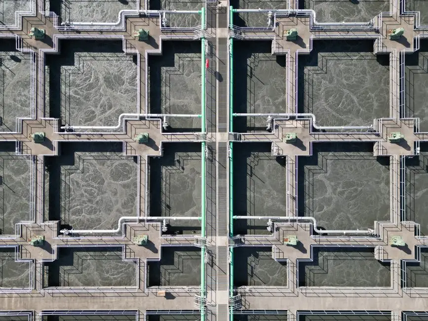
Designing to numbers rather than narrative is what separates a specifiable terminal water system from a permit-liability waiting to happen. The table below consolidates the operating envelope documented at large integrated-operator terminals handling mixed loading-rack, tank-bottom, and stormwater flows (HydropureWater field data, 2026).
| Parameter | Raw Terminal Influent | NPDES Effluent Limit (typical) | MBR Effluent (reuse-grade) |
|---|---|---|---|
| Oil & Grease (O&G) | 200–2,000 mg/L | ≤10–15 mg/L (30-day avg.) | <2 mg/L |
| Total Suspended Solids (TSS) | 100–500 mg/L | ≤30 mg/L | <1 mg/L |
| Biochemical Oxygen Demand (BOD₅) | 200–1,000 mg/L | ≤30 mg/L | <5 mg/L |
| Chemical Oxygen Demand (COD) | 500–3,000 mg/L | ≤100–125 mg/L | <30 mg/L |
| Linear Alkylbenzene Sulfonate (LAS) | Up to 400 mg/L (industrial) | Site-specific (often <1 mg/L) | <0.5 mg/L post-MBR |
| Turbidity | 50–500 NTU | ≤ effluent-specific | <1 NTU |
| Ammonia Nitrogen (NH₃-N) | 10–50 mg/L | Site-specific (≤1–10 mg/L) | <1 mg/L (nitrified) |
The NPDES oil and grease limit at petroleum terminals is typically 10–15 mg/L on a 30-day average, with a daily maximum not to exceed 20–30 mg/L depending on the permit region. BOD and TSS limits of 30 mg/L are common under 40 CFR 435 and equivalent state permits, though site-specific limits can be tighter where the receiving stream is sensitive.
The surfactant line deserves attention. Municipal headworks see <10 mg/L LAS; industrial surfactant operations and tank-cleaning operations at terminals see up to 400 mg/L (per Espinoza, LSU, 2004). That 40× spread is why our MBR engineering guide for detergent and surfactant wastewater treats MBR not as a luxury but as the load-bearing step for any terminal that handles surfactant-based cleaners or detergent washdowns. After biological treatment and disinfection with a properly sized chlorine dioxide generator, the effluent is suitable for landscape irrigation, dust suppression, or cooling-tower make-up.
What Technologies Does ExxonMobil Actually Use at Its Terminals?
ExxonMobil does not publish terminal-level P&IDs, but the unit operations documented in operating disclosures, permit filings, and engineering literature for major integrated-operator terminals are consistent. The following stack is what a process engineer should expect to find at a bulk-storage or marine terminal handling crude, refined products, and intermediates.
API separators and corrugated plate interceptors (CPI) are the baseline for primary oil recovery. DAF units are deployed upstream of biological treatment to strip emulsified oil and colloidal TSS that the API cannot break. Biological treatment — either conventional activated sludge or, increasingly, MBR — handles the dissolved organic and surfactant load. MBRs are favored at space-constrained coastal or urban terminals because the membrane barrier eliminates a separate clarifier and produces reuse-quality effluent in a smaller footprint.
Discharge is governed by EPA NPDES permits and site-specific limits set by the relevant state agency (Texas Railroad Commission, Louisiana DEQ, California RWQCB, etc.). Major terminal operators including ExxonMobil have reported zero routine water-quality violations at permitted outfalls in recent operating disclosures, though isolated non-compliance events tied to storm events above design capacity remain a documented industry risk (per EPA enforcement records, 2024–2025).
Slop oil and recovered hydrocarbons are not a waste stream in the disposal sense — they are recycled back into refinery feedstock or sold as off-spec fuel oil. Recovering this material typically offsets 15–30% of the terminal's annual water-treatment operating cost at sites handling more than 50,000 m³/yr of oily wastewater.
How to Specify a Terminal Wastewater Treatment System in 2026
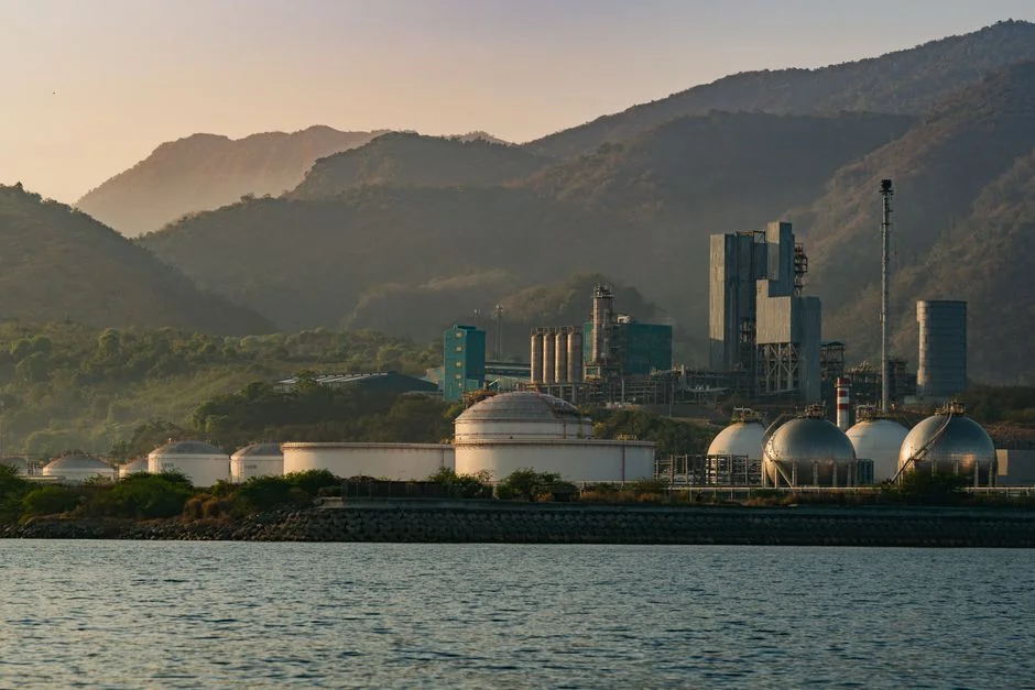
The engineering narrative above only matters if it converts into equipment the reader can put on a purchase order. The checklist below is the minimum specification envelope a B2B buyer should require on any 2026 terminal water-system bid.
First, match the treatment train to the flow regime. Hydrostatic test water is intermittent and high-volume; loading-rack wash is continuous and lower-volume but higher-load. A single train with adequate equalization is almost always more cost-effective than parallel dedicated systems, provided the equalization basin is sized for at least 24 hours of peak hydrostatic test inflow.
Second, specify the API separator for 30–60 minutes of residence time at peak flow, plus a 10% future-capacity margin. Include a CPI retrofit option if free-oil removal needs to climb above 99% for downstream membrane protection.
Third, specify a DAF for 90–95% TSS and emulsified oil removal. Confirm hydraulic loading of 4–25 m³/m²·h and air-to-solid ratios of 0.03–0.08 kg air/kg TSS. Add a pre-screen such as a rotary mechanical bar screen to protect downstream equipment.
Fourth, specify an MBR if footprint is constrained or if the effluent is intended for reuse (cooling-tower make-up, irrigation, dust suppression). Confirm membrane pore size ≤0.1 µm, MLSS operating range of 8,000–12,000 mg/L, and design flux of 15–25 L/m²·h.
Fifth, specify a chlorine dioxide generator for surface-water discharge or UV for reuse applications where residual oxidant cannot be tolerated. Pair the ClO₂ system with an automatic chemical dosing skid for consistent residual control.
Sixth, specify a plate-and-frame filter press for sludge dewatering. Target cake solids of 25–35% dry weight for stackable disposal or thermal treatment. Budget 0.8–1.5 kg polymer per kg dry solids for conditioning.
Frequently Asked Questions
What is the typical NPDES oil and grease limit at a petroleum terminal?
The NPDES oil and grease limit at most U.S. petroleum terminals is 10–15 mg/L on a 30-day average, with a daily maximum of 20–30 mg/L depending on the permit region and receiving-stream classification (per 40 CFR 435 and equivalent state permits).
How much LAS surfactant can a terminal wastewater biological system handle?
Acclimated activated-sludge or MBR systems at industrial sites have been documented treating up to 400 mg/L LAS in continuous operation, though shock loads above 200 mg/L without acclimation typically require MBR or moving-bed biofilm reactor (MBBR) polishing to maintain compliance (per the LSU biological treatment thesis, 2004).
Is MBR required, or is conventional activated sludge sufficient for a terminal?
Conventional activated sludge is sufficient for BOD and ammonia removal at most terminals. MBR becomes necessary when the site has a tight footprint, when the effluent is targeted for reuse (cooling-tower make-up, irrigation), or when influent LAS exceeds ~200 mg/L on a regular basis (per HydropureWater field data, 2026).
What is the difference between API and CPI oil-water separators?
An API (American Petroleum Institute) separator uses only gravity and residence time to separate free oil. A CPI (corrugated plate interceptor) adds inclined plates that shorten the oil-droplet rise path, increasing removal efficiency to 95–99% in a smaller footprint — at the cost of more frequent plate cleaning.