

How Does a UASB Reactor Work in Plant Terms?
How does a UASB reactor work? Influent enters at the bottom and flows upward at 0.5–1.5 m/h through granular anaerobic sludge, bacteria convert 80–95% of COD into methane-rich biogas, and a three-phase separator at the top retains biomass so no secondary clarifier is needed.
A UASB (Upflow Anaerobic Sludge Blanket) reactor treats high-strength wastewater through that upflow process in a single tall vessel. Bacteria convert 80–95% of COD into methane-rich biogas (65–75% CH₄) at 4–15 kg COD/m³/day. According to the US EPA, biogas runs 50 to 75 percent methane, and a well-granulated UASB bed sits in the upper half of that band. An internal three-phase separator retains biomass, so no secondary clarifier is required.
The vessel is typically 4–8 m tall. Influent enters a bottom distribution manifold and flows upward through self-immobilized granular sludge. Mature beds exceed 40 g/L MLSS, several times the concentration in an activated-sludge aeration tank. Biogas rises into an internal dome, clarified effluent overflows top weirs, and the granular bed stays in place.
Industrial buyers in 2026 still specify UASB for streams above 2,000 mg/L COD. Documented comparisons put energy use 40–60% below aerobic treatment. Excess sludge is 80–90% lower, and reactor volume is 25–40% of an equivalent activated-sludge train (anaerobic-digestion.com, 2026). Captured biogas can push the net energy balance positive, which mattered as industrial electricity prices in the EU and North America rose 8–22% over 2024–2025.
Operating references still cited in 2026 include New Belgium Brewing's 1,500 m³ brewery reactor and Mondi Kraft Paper's 5,000 m³ pulp unit in South Africa. Arla Foods runs a two-stage dairy system in Sweden. The Onça WWTP in Belo Horizonte handles roughly 2 m³/s of municipal flow. These four anchors bracket the load range the rest of this guide works through.
The Four Biochemical Stages Inside the Reactor
Anaerobic digestion inside a UASB is a four-stage microbial relay, and methanogenesis is the slowest leg. That stage sets the minimum hydraulic retention time. Mapping each stage to a position in the sludge blanket is what lets a specifier read a P&ID with confidence.
- Hydrolysis breaks complex polymers (proteins, lipids, carbohydrates) into soluble monomers. It occurs in the lower third of the sludge blanket, where long solids residence time supports the slow-growing hydrolytic bacteria. This is the rate-limiting step for particulate-heavy wastewaters such as raw slaughterhouse or food-processing effluent.
- Acidogenesis converts those monomers into volatile fatty acids (VFAs), hydrogen, and CO₂. It happens in the middle of the blanket where the organic load is still high but the biomass is acclimated. pH here typically reads 5.5–6.8, distinctly below the methanogenic zone above.
- Acetogenesis converts higher VFAs (propionate, butyrate) into acetate, hydrogen, and CO₂. This stage is the most sensitive to overload: a rising H₂ partial pressure stalls propionate oxidation. The symptom a designer first sees is VFA accumulation with falling pH, a classic warning that the methanogens are being outrun.
- Methanogenesis converts acetate and H₂/CO₂ into methane near the top of the blanket and inside the gas collector. Two archaeal groups do the work: acetoclastic methanogens (Methanosaeta, Methanosarcina) split acetate to CH₄ and CO₂, while hydrogenotrophic methanogens reduce CO₂ with H₂. The stage produces 65–75% of the biogas as CH₄ and governs the overall HRT, because the archaea double only every 3–10 days under mesophilic conditions.
Operators protect the methanogen population first. A 5°C drop below 20°C cuts overall COD removal by roughly 10–12% per 5°C step (anaerobic-digestion.com, 2026), and almost all of that loss sits on the methanogenic side. Solids needing deep digestion can stay in the bed far longer than the liquid; Wikipedia's UASB digest notes solids requiring a high degree of digestion can remain in the reactors for periods up to 90 days.
Cold wastewaters below 20°C therefore push designers toward EGSB or IC variants, which use 5–10 m/h upflow to keep biomass in contact when kinetics slow. Daily VFA and alkalinity checks are the cheapest insurance during the first months of operation. Most plants we size for food and beverage COD run mesophilic and stay at the lower end of the OLR window until the blanket is fully granulated.
Inside the Reactor: The Four Physical Zones
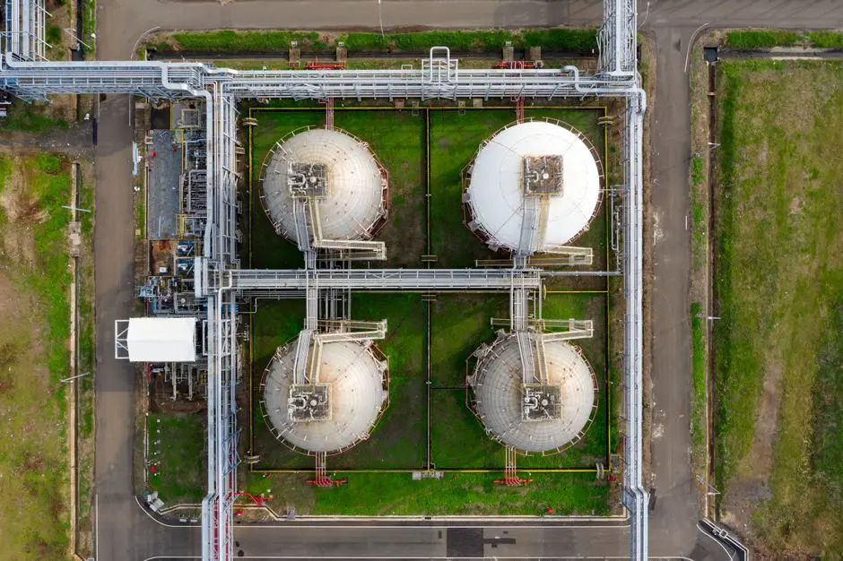
Every UASB stacks four physical zones, each with a defined hydraulic job. Once the zones are mapped, vendor drawings become much easier to compare.
- Influent distribution zone. The bottom of the reactor uses a header pipe, nozzle manifold, or slotted plate to spread flow across the full cross-section. Poor distribution is the single most common cause of dead zones and channeling in operating plants. The symptom is granular bed caking on one side and washout on the other. A common design rule is one distribution point per 2–5 m² of floor area for industrial-strength waste.
- Sludge blanket zone. This zone is 40–60% of the reactor volume in a mature system and contains two layers. A dense bed of 1–3 mm granules with settling velocity above 25 m/h sits at the bottom, and a flocculent top layer handles newer growth and entrapment. The bed physically expands and contracts with upflow velocity and gas production — a healthy blanket rises and falls 0.3–1.0 m over a diurnal cycle.
- Gas-solids-liquid (three-phase) separator. Located near the top of the vessel, this is the mechanical component that defines a UASB versus a simple upflow digester. A deflector baffle below the gas collector intercepts rising biogas, and an inverted hood above channels gas into the collector dome. Liquid makes a 180° turn under the hood; washed solids drop back to the blanket, and clarified effluent spills over outlet weirs. Without this device, biomass would wash out and the secondary clarifier everyone is trying to avoid would come back into the design.
- Effluent collection zone. The top launder or peripheral weir collects the clarified liquid. Effluent recycle to the bottom is common on industrial units and serves two purposes: it raises the upflow velocity into the 0.5–1.5 m/h operating window during low-flow periods, and it improves mixing at the distribution zone. Peak upflow can briefly reach 3 m/h without granule washout, but sustained velocities above this risk bed fluidization and loss of biomass.
When a vendor datasheet claims "internal clarifier" or "no secondary clarifier required," the three-phase separator geometry is doing the work. Scrutinize that drawing detail during equipment comparison.
UASB reactor three phase separator design: what the drawing must show
Patent EP1740505A1 documents the classic separator arrangement for upflow sludge bed reactors: the bottom part of the separator consists of overlapping biogas collection hoods and baffle plates, with biogas piped away via openings in the endplate. Above the hoods, a gas-free, relatively quiet settling zone is created, so sludge settles there instead of escaping with the effluent. Openings between the hoods and the baffle plates return settled sludge to the reactor section, and collection gutters at the top discharge the clarified water. Check all four features — hoods, quiet zone, sludge-return openings, and effluent gutters — on every vendor GA drawing before comparing prices.
What Are Typical UASB Design Values?
Typical UASB design values for industrial high-strength wastewater use OLR 4–15 kg COD/m³/day, HRT 12–24 h, normal upflow 0.5–1.5 m/h, and mesophilic temperature 30–37°C. Modern SGBR layouts can cut HRT to 4–8 h. Process engineers lift these ranges straight into feasibility memos and RFQ replies, and values outside the table need a written supplier justification. For a deeper take-off sheet, use the UASB Reactor Design Parameters: 2026 Engineering Reference guide before you freeze vessel volume.
| Parameter | Industrial UASB range | Notes |
|---|---|---|
| Influent COD | 2,000–20,000 mg/L | Commercial sweet spot; below ~1,000 mg/L the economics weaken (Aiyuk et al., 2010) |
| OLR | 4–15 kg COD/m³/day | Vs. 1–3 kg COD/m³/day for conventional anaerobic digesters |
| HRT | 12–24 h conventional; 4–8 h SGBR/modern | Set by methanogen growth rate, not by influent concentration |
| Upflow velocity | 0.5–1.5 m/h normal; 3 m/h peak | Above 3 m/h sustained, expect granule washout |
| Temperature | 30–37°C mesophilic optimum | ~10–12% COD loss per 5°C drop below 20°C; below 20°C prefer EGSB/IC |
| Biogas yield | 0.3–0.5 m³ per kg COD removed | 65–75% CH₄ content |
| MLSS in mature bed | >40 g/L | Several times typical activated-sludge concentration |
| Seeding | 10–15 g VSS/L; 20–30% of volume | 24–48 h recirculation before feeding |
| N/P removal | <15% each | Discharge compliance will not be met by UASB alone |
UASB reactor design parameters for industrial wastewater: the RFQ shortlist
UASB RFQ sheets should lock influent COD range, design OLR, HRT, upflow velocity, temperature, and seeding dose, and name the polishing train needed for N and P. EPC search strings still run long and specific — one recurring query reads "parameters for upflow anaerobic sludge blanket uasb reactor for esterification process waste water treatment." The engineering behind that string is sector-neutral: esterification effluent answers to the same OLR, HRT, and upflow discipline as brewery or dairy streams before vessel volume is frozen.
Two 2026 design flags matter most. First, temperature: standard UASB below 20°C needs EGSB or IC variants. Those units use 5–10 m/h upflow to offset slower kinetics and deliver 15–25% better cold-temperature COD removal (anaerobic-digestion.com, 2026). For scale on the loading side, Wikipedia's process digest lists typical EGSB loading rates at 15–30 kg COD/m³/day, roughly double the conventional UASB window. Second, nutrients: nitrogen and phosphorus removal typically stays under 15%, so downstream polishing is mandatory wherever the permit limits total N or total P.
The Aiyuk et al. (2010) low-strength case shows what happens below the commercial range. At 522 mg/L influent COD, the reactor still removed 80%. Yet 70% of that COD was captured as suspended solids, sludge had to be discharged every ~100 days, and each discharge destabilized the methanogenic community.
Selection checklist before you freeze the vessel volume:
- Confirm influent COD stays above ~2,000 mg/L for most of the year, not only at peak campaigns.
- Size OLR inside 4–15 kg COD/m³/day and keep sustained upflow at or below 1.5 m/h.
- Budget heat if the stream sits below 20°C, or switch the concept to EGSB/IC.
- Plan seeding at 10–15 g VSS/L filling 20–30% of volume, plus 24–48 h recirculation.
- Reserve downstream polishing for residual COD, TSS, N, and P — UASB alone will not meet a nutrient permit.
- Scrutinize three-phase separator geometry on every vendor drawing before comparing prices.
- Count biogas at 0.3–0.5 m³ per kg COD removed when you build the energy balance.
How a UASB Reactor Fits Into a Plant Train
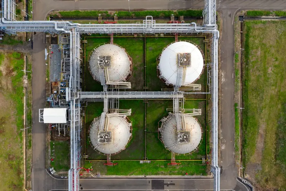
A UASB reactor works as the core biological step in a multi-stage train, never as a stand-alone discharge solution. The standard 2026 industrial configuration runs: headworks screening → flow equalization → FOG/colloid removal → UASB → aerobic or membrane polishing → disinfection.
Pre-treatment is non-negotiable for industrial streams. A rotary bar screen for headworks removes rags, plastics, and large solids that would otherwise accumulate in the granular bed. A DAF pre-treatment system upstream drops FOG and colloidal load. That matters most for dairy, food, and slaughterhouse streams, where lipids blind the granular bed and trigger the same sludge-buildup failure documented in the Aiyuk study. Equalization follows: a buffer tank smooths COD and hydraulic peaks, because UASB tolerates surges but not sustained upflow above 3 m/h, which causes granule washout.
Post-treatment is where the discharge permit is actually met. UASB effluent typically retains 15–30% of incoming organics, nearly all escaping suspended solids, plus essentially all nitrogen and phosphorus. Two common 2026 polishing routes remain. An MBR polishing step with submerged PVDF membranes (0.1–0.4 μm nominal pore) targets near-reuse quality, while DAF plus disinfection covers direct discharge. Compact sites that need packaged aerobic polishing after anaerobic pretreatment sometimes evaluate an Underground Package Sewage Treatment Plant (WSZ Series) as the downstream module.
Startup sequencing across the train matters as much as the UASB itself. Seed the anaerobic step first, then commission polishing once anaerobic effluent quality stabilizes. Plants that start both stages on day one usually fight suspended solids in the membrane or DAF unit for weeks.
For hybrid calculation basis, see the hybrid UASB designs for high-strength wastewater spec guide. The UASB+MBR design for fermentation wastewater engineering guide walks through a real 2025–2026 plant case.
Where polishing is MBR versus conventional activated sludge, the MBR vs activated sludge comparison lays out operating-cost differentials. For a live biogas project on citrus-processing wastewater, the citrus wastewater biogas project in Brazil is the most recent public example scheduled for late 2026.
Arla Foods Vimmerby and Mondi Kraft South Africa show the same pattern. UASB strips 70–85% of the organic load as the workhorse biological step. A downstream polishing train then handles nutrients, residuals, and disinfection.
Real-World UASB Performance Benchmarks
Named installations are the cleanest evidence that UASB works at scale. The four below cover the industrial COD range UASB serves best, from 2,000 mg/L at the low end to above 10,000 mg/L at the high end (anaerobic-digestion.com, 2026).
| Installation | Reactor volume | Influent COD | Sector |
|---|---|---|---|
| New Belgium Brewing, Colorado | 1,500 m³ | 2,000–6,000 mg/L | Brewery |
| Arla Foods, Vimmerby, Sweden | Two-stage UASB | >10,000 mg/L | Dairy (whey) |
| Mondi Kraft Paper, South Africa | 5,000 m³ | 3,000–5,000 mg/L | Pulp & paper |
| Onça WWTP, Belo Horizonte, Brazil | Multiple reactors | Municipal (~2 m³/s) | Sanitary |
The COD span these four represent — roughly 2,000 to over 10,000 mg/L — is the 2026 commercial sweet spot. Below 1,000 mg/L, granule formation is weak and the Aiyuk et al. (2010) failure mode reappears. Above 20,000 mg/L, free ammonia or VFA inhibition becomes a real risk, so staged configurations or EGSB are preferred there.
Benchmarks only transfer when the load profile transfers. A brewery reactor running 2,000–6,000 mg/L campaigns does not size a dairy plant with sustained 10,000 mg/L whey. Match influent COD distribution, temperature, and FOG load before quoting any of these four as precedent in a feasibility memo.
Energy recovery drives the 2026 ROI case. At 0.3–0.5 m³ biogas per kg COD removed and 65–75% CH₄, biogas yield is substantial. A 1,500 m³ UASB treating 5,000 mg/L influent at 6 kg COD/m³/day OLR can offset a meaningful share of plant heat or power. That is what turns UASB from a treatment cost into a process utility.
Who This Is For and Next Step
UASB fits plant engineers and EPC teams sizing anaerobic treatment for industrial COD above 2,000 mg/L. Food, dairy, brewery, and pulp streams that can use biogas on-site fit best. Sites with sustained wastewater below ~1,000 mg/L COD should look elsewhere, and cold streams that will not be heated should start with EGSB/IC instead. If you already have influent COD, temperature, and discharge limits, send them through a UASB process design inquiry and we can check whether standard UASB, EGSB, or a hybrid train fits the load.
Frequently Asked Questions
How does a UASB reactor work step by step?
Influent enters the bottom through a distribution manifold and flows upward through granular anaerobic sludge at 0.5–1.5 m/h. Four anaerobic digestion stages convert organics into biogas with 65–75% CH₄. A three-phase separator at the top deflects biogas into an internal dome, returns washed solids to the blanket, and routes clarified effluent over weirs. That geometry replaces the secondary clarifier used in conventional activated-sludge plants.
What is the typical COD removal efficiency of a UASB reactor?
Industrial UASB systems achieve 80–95% COD removal on influent in the 2,000–20,000 mg/L range. The Aiyuk et al. (2010) study documented 80% removal at a much weaker 522 mg/L influent. That case also showed the limit of running UASB below its commercial range: 70% of the COD ended as captured suspended solids discharged about every 100 days.
What is the difference between UASB and EGSB reactors?
EGSB (Expanded Granular Sludge Bed) reactors operate at much higher upflow velocities — 5–10 m/h versus 0.5–1.5 m/h for standard UASB — which expands the granular bed and improves wastewater-biomass contact. Wikipedia's digest lists typical EGSB loading rates at 15–30 kg COD/m³/day, well above the 4–15 kg COD/m³/day UASB window. EGSB delivers roughly 15–25% better COD removal on cold wastewaters (10–20°C) because enhanced hydraulic mixing compensates for slower methanogenic kinetics (anaerobic-digestion.com, 2026).
How long does it take to start up a UASB reactor?
Startup begins with granular sludge seeding at 10–15 g VSS/L, filling 20–30% of reactor volume. Recirculate for 24–48 hours before introducing wastewater. Full granulation — well-formed 1–3 mm granules settling above 25 m/h — typically takes 2–6 months, and Wikipedia's process digest puts blanket maturity at around three months, inside that window. Wastewater composition, temperature, and loading progression set the pace.
Can a UASB reactor work at low temperatures?
Standard UASB performance drops approximately 10–12% for every 5°C reduction below 20°C, so a site operating consistently below 15–20°C should plan for an EGSB or IC variant instead. EGSB's higher upflow velocity (5–10 m/h) maintains biomass contact with substrate even when reaction rates slow, extending the viable temperature range about 3–5°C lower than conventional UASB.
How much biogas does a UASB reactor produce per kg of COD removed?
Plan on 0.3–0.5 m³ of biogas per kg COD removed, with 65–75% CH₄ content in a healthy granular bed. According to the US EPA, biogas overall runs 50 to 75 percent methane, so UASB beds sit in the upper half of the band. A 1,500 m³ reactor at 5,000 mg/L influent and 6 kg COD/m³/day OLR produces enough biogas to offset a meaningful share of plant heat or power.