Why Gelatin Wastewater Is Hard to Treat
Gelatin production wastewater carries a heavy organic load and a large suspended-solids fraction, which causes conventional biological secondary treatment to underperform on this stream. The 2019 Heliyon comparative study on real gelatin plant effluent (Kobya et al., sciencedirect.com) found that the heavy COD load and high suspended solids together produce low performance in secondary treatment, regardless of biological configuration.
The pollutant mix in a gelatin plant is unusually wide. Upstream sources include soaking and liming of hides, degreasing, bone/acid treatment, washing of the cooked stock, and evaporation condensates. Each contributes a different fraction: soluble proteins and amino acids from liming, emulsified fats from degreasing, fine suspended collagen particles from washing, and warm condensates from evaporation. The result is a stream that is simultaneously high in dissolved COD, high in colloidal and suspended solids, and warm—conditions that defeat a standard activated-sludge basin designed for municipal sewage.
No single unit operation will hit a discharge or reuse limit. The article's central question is whether electrocoagulation (EC) with aluminum electrodes can outperform chemical coagulation (CC) with aluminum salts, and how either fits into a complete train that a gelatin plant can build and operate.
Electrocoagulation vs Chemical Coagulation: The Headline Data
The Heliyon study on real gelatin plant effluent reported 73.6% COD removal with electrocoagulation using aluminum electrodes versus 55.6% with chemical coagulation using aluminum salts, with the comparison made at a matched aluminum dose (S3, 2019, sciencedirect.com). That 18-percentage-point gap serves as the anchor data point.
The mechanism behind the gap is reported in the same paper: SEM-EDS analysis of the EC sludge showed in-situ formation of zeolites, a sorbent phase that does not appear when aluminum is simply dosed as a salt. Zeolite formation gives the EC floc an additional surface for adsorbing dissolved protein and small colloids, which is why the same gram of aluminum does more work in an EC cell than in a jar test. CC flocs, by contrast, rely on charge neutralization and sweep flocculation alone.
The broader electrochemical envelope reported on a related high-COD feed—petroleum refinery wastewater—reached 99.5% COD removal and 94.2% oil removal at 12 kWh/m³, pH 7, 50 minutes, and 10.5 V, using 4 aluminum and 4 iron electrodes at 2 cm spacing (S1, Wasit University, doi.org). Those are an upper-bound reference, not a guarantee: the S1 study used a 710 mg/L COD refinery feed, not gelatin plant effluent, and the cited 12 kWh/m³ is the only energy benchmark in the supplied research. A buyer planning a 2026 EC unit should request kWh/m³ at design load from the supplier, rather than relying on the S1 number directly.
| Parameter | EC with Al electrodes (S3, 2019) | CC with Al salts (S3, 2019) | EC reference, refinery feed (S1) |
|---|---|---|---|
| Feed | Real gelatin plant effluent | Real gelatin plant effluent | Petroleum refinery wastewater |
| COD removal | 73.6% | 55.6% | 99.5% |
| Oil removal | Not reported | Not reported | 94.2% |
| Energy use | Not reported | N/A | 12 kWh/m³ |
| Mechanism highlight | In-situ zeolite formation (SEM-EDS) | Charge neutralization only | Al/Fe sacrificial electrodes |
| Scope caveat | Laboratory scale, gelatin feed | Same matched dose as EC arm | Different feed — upper-bound reference |
EC wins on COD removal efficiency in matched-dose trials, but it requires DC power, electrode replacement, and sludge handling that CC does not. CC remains attractive where the plant has a working biological stage downstream and only needs the coagulation step to knock down suspended solids and a portion of the COD.
Building a Full Treatment Train for 2026
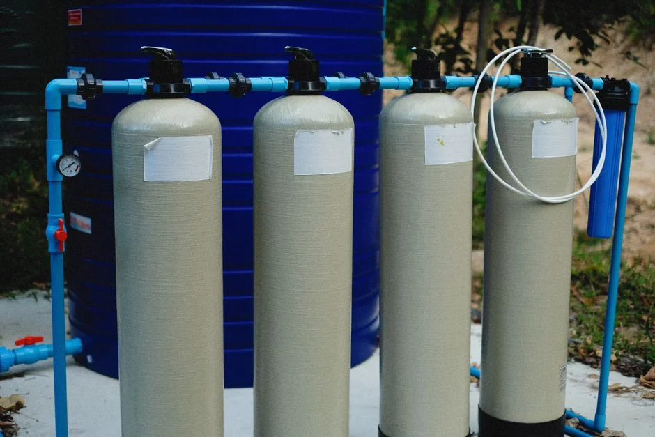
A single coagulation step is insufficient to treat gelatin effluent effectively. The Heliyon study explicitly notes that gelatin effluent is high in both dissolved COD and suspended solids, so neither a primary step nor a secondary biological step alone is adequate (S3, 2019). The train that fits the data, in order, is: rotary bar screen → flow equalization → primary separation (DAF or lamella clarifier) → coagulation and biological stage → membrane polishing (UF or MBR) → disinfection.
The first three steps handle what the academic EC/CC papers largely ignore. A rotary bar screen for headworks protection removes large debris and protects downstream pumps. Equalization dampens the warm, high-strength spikes from batch washing and evaporation. The primary separation is where an industrial DAF system for primary separation earns its place: it lifts the floatable protein and lipid fraction and drops a large share of the suspended solids before any chemical or biological stage sees them, cutting both chemical demand and biological loading. Readers can review the underlying process in this piece on how a pressure flotation (DAF) system works.
After primary separation, the residual COD is slowly biodegradable, which is why a MBR membrane bioreactor for COD polishing or a conventional activated-sludge basin followed by UF is the right polishing choice. MBR gives the smallest footprint and reuse-quality effluent, while conventional activated sludge plus UF is easier to retrofit into an existing tank farm. Either way, the permeate still needs disinfection before reuse or discharge, and the concentrate stream must be returned to sludge handling. For broader technology context, this 2026 buyer guide to COD/BOD removal technologies maps the same train against other high-COD industries, and the parallel starch wastewater COD removal engineering guide shows how the same unit operations are applied to a related protein-rich feed.
Equipment Selection: Where HydropureWater Fits
The train in the previous section maps to specific equipment a process engineer can put on a 2026 RFQ. The headworks step is a rotary bar screen for headworks protection. Primary separation of suspended solids and floatables is an industrial DAF system for primary separation. Polishing is either a MBR membrane bioreactor for COD polishing or a hollow-fiber UF polishing system. The resulting sludge is dewatered with a filter press for gelatin sludge dewatering.
Catalog capacity ranges are: DAF 4–300 m³/h across 13 models; MBR 10–2,000 m³/day; UF 2,000–40,000 L/h. The reader should sanity-check these against their own peak and average flow, then ask the supplier for a guaranteed effluent at design load rather than a generic curve.
Choose MBR when the plant needs the smallest footprint and reuse-quality permeate, and the operations team is comfortable with membrane cleaning. Choose conventional activated sludge plus UF when existing concrete tanks can be retrofitted and the team prefers biological process control over membrane maintenance. No catalog product on this site is an electrocoagulation reactor: if the reader wants the 73.6% COD removal route from the Heliyon study (S3, 2019), an EC unit must be sourced separately and integrated as a coagulation step ahead of the DAF or as a polishing step after biological treatment. This is a separate procurement decision the engineer should plan for in 2026.
| Train step | Equipment | Published capacity range | Role |
|---|---|---|---|
| Headworks | Rotary bar screen (GX) | Not published as a single range in supplied research | Debris removal, pump protection |
| Primary separation | DAF unit | 4–300 m³/h | Floatables, oil/grease, suspended solids |
| Biological / coagulation | Sourced separately (e.g., EC reactor, activated sludge) | Site-specific | Dissolved COD reduction |
| Polishing | MBR or UF | MBR 10–2,000 m³/day; UF 2,000–40,000 L/h | Residual COD, reuse-quality effluent |
| Sludge | Plate-and-frame filter press | Site-specific | Sludge dewatering before disposal |
Sizing, Operating Costs and the 2026 Buyer's Checklist
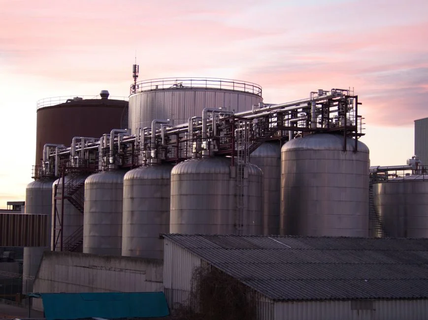
The buyer must collect a defined set of inputs before any supplier sizes a system. These qualitative variables include average and peak flow, influent COD, BOD, TSS, pH, temperature, fat/oil/grease fraction, hours of operation per day, and the target effluent limits. The Heliyon study (S3, 2019) does not publish a typical influent range, so the engineer should measure at the discharge of each upstream unit rather than rely on a generic table.
On energy, the only benchmark in the supplied research is 12 kWh/m³ from the S1 petroleum-refinery EC study. Real gelatin-plant EC energy use will depend on influent COD and current density; the buyer should request kWh/m³ at design load, not just nameplate kW, for both the EC unit (if used) and the MBR or UF polishing stage.
A 2026 supplier should be asked, in writing, for: a pilot or reference list on gelatin or similar protein effluent; a guaranteed COD removal at design load; electrode or aluminum consumption rate (kg Al per m³ treated); sludge yield (m³ per m³ treated) and sludge characterization; and an OPEX breakdown covering power, electrodes, chemicals, and sludge hauling. Additional hardware on a complete train may include a high-efficiency sedimentation tank for primary clarification and an automatic chemical dosing system for coagulant control.
The decision rule is direct: choose EC when the plant has high COD, limited footprint, and no existing biological stage. Choose CC plus DAF plus MBR when the plant wants proven equipment, lower capex per m³/h, and an existing biological operations team. In either case, the train should include primary separation, biological or EC reduction, membrane polishing, and sludge dewatering.
Frequently Asked Questions
How much does a gelatin wastewater treatment system cost in 2026?
Capital cost depends on flow, influent load, and the chosen train; the supplied research does not publish a price for a gelatin plant system. A buyer should request a budgetary quote broken out by unit (DAF, MBR or UF, filter press, optional EC reactor) and ask the supplier to state the guaranteed COD removal at design load inside that quote. Use the sizing inputs in the previous section to compare two or three suppliers on a like-for-like basis.
Which treatment technology should a gelatin plant specify first?
Specify a train, not a single unit. The Heliyon study (S3, 2019) shows that neither primary nor secondary treatment alone is sufficient for gelatin effluent, because the stream is high in both dissolved COD and suspended solids. The recommended 2026 order is rotary bar screen → equalization → DAF or lamella clarifier → coagulation/biological stage → UF or MBR polishing → disinfection. If the plant wants the 73.6% COD removal route reported in the same paper, an EC reactor is integrated as the coagulation step and must be sourced separately from the rest of the train.
What is the difference between electrocoagulation and chemical coagulation for gelatin effluent?
Both use aluminum, but the Heliyon study (S3, 201