Why Pressure Flotation? The Problem It Solves in Industrial Wastewater
Industrial metalworking facilities and semiconductor fabs often face regulatory fines exceeding $50,000 per month when total suspended solids (TSS) concentrations in effluent surpass 200 mg/L. For example, a semiconductor fab in Taiwan recently struggled with 200 mg/L TSS in its effluent, which not only violated local discharge limits but also fouled downstream membrane systems, leading to an additional $15,000 in monthly maintenance costs. In these high-stakes environments, traditional sedimentation is often insufficient because the contaminants—such as emulsified oils, fine metal hydroxides, and light organic fibers—have densities too close to that of water to settle effectively within a reasonable footprint.
Pressure flotation, commonly referred to as Dissolved Air Flotation (DAF), is the critical solution for industries where gravity-based separation fails. In metalworking, influent challenges typically involve 500–2,000 mg/L TSS and 100–500 mg/L of fats, oils, and grease (FOG), along with heavy metals like copper (Cu), nickel (Ni), and chromium (Cr). Unlike clarifiers that rely on settling velocity (Stokes' Law), ZSQ series DAF systems for industrial wastewater treatment use buoyant forces to lift particles to the surface, significantly reducing the required hydraulic retention time (HRT) and equipment footprint.
| Feature | Pressure Flotation (DAF) | Sedimentation (Clarifier) | Membrane Filtration (UF/MF) |
|---|---|---|---|
| Target Contaminants | Low-density solids, FOG, metal hydroxides | High-density settleable solids | Colloidal and dissolved solids |
| Removal Efficiency (TSS) | 95% – 99% | 60% – 85% | 99.9% |
| Footprint | Compact (high overflow rate) | Large (requires long settling time) | Very Compact |
| Sensitivity to FOG | Excellent (FOG aids flotation) | Poor (FOG causes sludge bulking) | Very Poor (FOG fouls membranes) |
| Energy Demand | Moderate (pressurization pump) | Low (gravity based) | High (transmembrane pressure) |
The 3-Stage Pressure Flotation Process: A Step-by-Step Breakdown
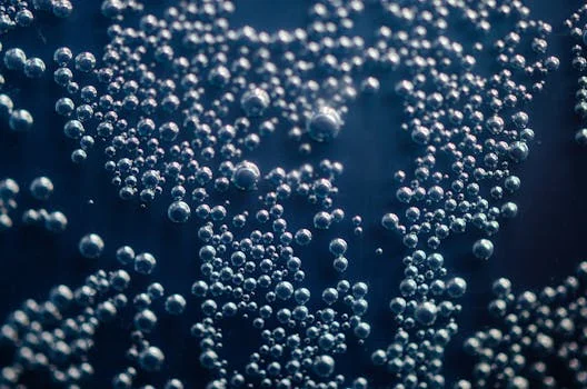
The efficiency of a pressure flotation system depends on the controlled release of air-saturated liquid, which creates microbubbles through a process known as nucleation. The mechanism is analogous to opening a pressurized soda bottle: when the pressure is suddenly released, the dissolved gas transitions from a liquid state back to a gaseous state, forming millions of tiny bubbles. In an industrial DAF, this process is engineered across three distinct stages to ensure maximum contaminant recovery.
Stage 1: Air Dissolution
In the first stage, a portion of the clarified effluent (typically 20–50% of the influent flow) is diverted to a recycle stream. This water is pressurized to 40–70 psi (2.7–4.8 bar) using a centrifugal pump and directed into a saturation tank. Compressed air is introduced into this tank, where it dissolves into the water. According to Henry’s Law, the solubility of air in water increases linearly with pressure. At 60 psi, water can hold significantly more air than at atmospheric pressure, creating a supersaturated solution (Zhongsheng field data, 2025).
Stage 2: Bubble Formation and Nucleation
The supersaturated recycle water is then reintroduced into the main influent stream at the entrance of the flotation tank through specialized pressure-reducing valves or nozzles. As the pressure drops from 60 psi to atmospheric pressure in less than one second, the dissolved air precipitates out of the solution. This "extremely short bubble formation period" (as noted in recent mechanical analyses) results in the creation of microbubbles ranging from 20 to 100 μm in diameter. These bubbles are small enough to provide a massive surface area for particle attachment without creating the turbulence that would break apart fragile chemical flocs.
Stage 3: Particle-Bubble Attachment and Separation
Within the contact zone of the flotation tank, the microbubbles collide with and adhere to the suspended contaminants. This attachment is driven by hydrophobic forces and the trapping of bubbles within the floc structure. The combined density of the particle-bubble aggregate becomes significantly lower than that of water, causing it to rise to the surface at a rate of 0.5–2 cm/s. In the separation zone, a 10–30 cm thick float layer (scum) forms, which is then mechanically skimmed into a sludge hopper. The clarified water is discharged from the bottom of the tank, often through a series of underflow baffles to prevent solids carryover.
| Particle Size (μm) | Bubble Size (μm) | Attachment Efficiency (%) | Rise Velocity (cm/s) |
|---|---|---|---|
| 10 | 30 | 30% | 0.2 |
| 50 | 30 | 82% | 0.8 |
| 100 | 50 | 95% | 1.5 |
| 250 (Flocculated) | 50 | 98%+ | 2.2 |
Engineering Parameters That Determine DAF Performance
Optimal gas-solid (G/S) ratios for industrial wastewater clarification typically range from 0.01 for heavy metal hydroxides to 0.10 for light fats, oils, and grease (FOG). Engineers must balance several "dials" to ensure the system handles fluctuating influent loads without compromising effluent quality. The primary parameters include the G/S ratio, recycle ratio, and hydraulic retention time (HRT).
Gas-Solid (G/S) Ratio Calculation
The G/S ratio is perhaps the most critical design parameter. It represents the mass of air available per mass of solids to be removed. For metal-containing wastewater, a G/S ratio of 0.01–0.05 is standard, whereas lighter organic solids require 0.05–0.1. The ratio is calculated as follows:
G/S = (C_s * Q_r) / (C_i * Q_i)
Where C_s is the air solubility at a given pressure, Q_r is the recycle flow rate, C_i is the influent solids concentration, and Q_i is the influent flow rate. If the influent TSS spikes, operators must increase the recycle ratio or the saturation pressure to maintain the target G/S ratio.
Pressure and Recycle Ratio Optimization
While higher pressure (up to 70 psi) increases the volume of dissolved air, it also increases energy consumption and can lead to shearing of flocs if the pressure drop is too violent. Most industrial systems operate optimally at 50–60 psi with a recycle ratio of 20–30% for standard TSS removal. For high-concentration streams (e.g., pulp and paper), the recycle ratio may be increased to 50% to provide sufficient bubble density.
| Saturation Pressure (psi) | Air Solubility (mg/L at 20°C) | Energy Cost (Est. $/m³) | Typical Application |
|---|---|---|---|
| 40 | 55 | $0.04 | Municipal Pre-treatment |
| 55 | 78 | $0.07 | Food Processing (FOG) |
| 70 | 102 | $0.12 | Heavy Metal Recovery |
Turbulence and Multichamber Design
To maximize collision efficiency, the Reynolds number within the contact zone should be kept below 2,000. Modern multichamber flotation units enhance performance by separating the initial mixing zone from the flotation zone. This design reduces internal turbulence by up to 40% compared to single-tank units, which is essential for how DAF integrates into semiconductor wastewater treatment where fine metal precipitates are easily disturbed.
Real-World Performance: DAF Removal Rates by Industry and Contaminant
Real-world operational data indicates that Dissolved Air Flotation (DAF) systems consistently achieve over 95% removal of suspended solids in food processing applications. However, performance varies significantly based on the chemical nature of the contaminant and the effectiveness of pre-treatment conditioning. DAF is a physical separation process, meaning it requires PLC-controlled chemical dosing for DAF optimization to coagulate and flocculate dissolved or colloidal particles before they enter the flotation tank.
| Industry | Contaminant | Influent Conc. (mg/L) | Removal Rate (%) | Operational Notes |
|---|---|---|---|---|
| Metalworking | TSS / Cu / Ni | 500 – 2,000 | 95% – 98% | Requires pH adjustment to 8.5 |
| Food Processing | FOG / TSS | 200 – 1,500 | 90% – 97% | See DAF systems for FOG and oil removal |
| Pulp & Paper | Fiber / COD | 1,000 – 5,000 | 90% – 95% | High recycle ratio (50%) required |
| Petrochemical | Free & Emulsified Oil | 100 – 500 | 92% – 98% | Explosion-proof motors required |
| Municipal | Algae / TSS | 50 – 200 | 85% – 95% | Effective for low-density algae |
While DAF is exceptionally effective for particulate matter, it has inherent limitations regarding dissolved contaminants. Soluble COD (Chemical Oxygen Demand) removal is typically limited to 10–20% unless those organics are adsorbed onto flocs. For high-strength wastewater, DAF is most effective as a pre-treatment step to protect downstream biological reactors or membrane systems from solids and oil loading.
Common DAF Failure Modes and How to Fix Them
Failure to maintain air saturation pressures between 40 and 70 psi is the primary cause of oversized bubble formation, which reduces particle-bubble collision efficiency by up to 60%. Operators must be trained to recognize the visual cues of system imbalance, such as a "boiling" surface in the flotation tank (indicating bubbles are too large) or a cloudy effluent (indicating poor flocculation or low G/S ratio).
| Symptom | Likely Cause | Solution |
|---|---|---|
| White water looks "milky" but solids don't float | Poor chemical conditioning / Wrong pH | Perform jar test; adjust coagulant dose or pH. |
| Large bubbles (>2mm) breaking the surface | Saturation pressure too low / Nozzle wear | Increase pressure to 60 psi; inspect nozzles for erosion. |
| Thin, watery float layer | Skimmer speed too high / Low solids load | Reduce skimmer frequency; check influent TSS. |
| Rising TSS in effluent | Short-circuiting / High HRT turbulence | Check for blocked baffles; reduce influent flow rate. |
| Saturation tank "burping" air | Air release valve failure | Clean or replace the automatic air release valve. |
A robust maintenance schedule is essential for long-term reliability. Daily tasks should include checking pressure gauges and inspecting the float layer consistency. Weekly, operators should verify the air saturation efficiency by sampling the "white water" in a graduated cylinder; it should stay milky for at least 60 seconds. Monthly, the saturation tank and nozzles must be inspected for scaling or biological fouling, especially in food processing applications where organic buildup is common.
DAF System Costs: CAPEX, OPEX, and ROI by Flow Rate
The total cost of ownership for a 50 m³/h DAF system typically includes a capital expenditure of approximately $100,000 and an operational cost of $0.08 to $0.28 per cubic meter of treated water. While the initial investment is higher than that of a simple sedimentation tank, the return on investment (ROI) is often realized through significantly lower sludge disposal costs and the elimination of regulatory fines.
| Flow Rate (m³/h) | Equipment CAPEX ($) | Installation Cost ($) | Total CAPEX ($) |
|---|---|---|---|
| 10 | $35,000 | $10,000 | $45,000 |
| 50 | $80,000 | $20,000 | $100,000 |
| 100 | $140,000 | $35,000 | $175,000 |
| 200 | $250,000 | $60,000 | $310,000 |
OPEX Components
Operating expenses are driven by three factors: energy, chemicals, and maintenance. Energy costs for the recycle pump and compressor range from $0.05–$0.15/m³. Chemical costs (coagulants like PAC and flocculants like PAM) range from $0.02–$0.10/m³ depending on the influent load. Because DAF produces a thicker sludge (2–5% solids) compared to sedimentation (0.5–1% solids), the volume of sludge for disposal is reduced by up to 50%, providing a major OPEX saving (Zhongsheng field data, 2025).
ROI Framework
To calculate the payback period, facilities should compare the DAF's total cost against the "cost of doing nothing." For a 50 m³/h system costing $100,000, if the system eliminates $30,000/year in TSS fines and saves $10,000/year in sludge hauling, the payback period is 2.5 years. For more details on budgeting, refer to the engineering specs and cost data for sewage treatment equipment.
Frequently Asked Questions
Q: What’s the difference between pressure flotation and dissolved air flotation (DAF)?
A: Dissolved Air Flotation and pressure flotation are synonymous terms describing the process of using dissolved air to float particulate matter to the surface of a treatment tank. Both rely on the principle of increasing air solubility under pressure (40–70 psi) and releasing it to form microbubbles.
Q: Can DAF remove dissolved metals like arsenic or chromium?
A: No. DAF is a physical separation process. It can only remove metals that have been precipitated into solid form (e.g., metal hydroxides). This requires pre-treatment with chemicals like lime or sodium hydroxide to shift the pH and form insoluble particles before flotation.
Q: What’s the optimal pH for DAF?
A: For most TSS and FOG removal, a pH of 6.5–8.5 is ideal. If you are specifically targeting metal removal, the pH must be adjusted to the specific precipitation point of the target metal, usually between 8.0 and 9.5. Extremely high or low pH can destabilize the microbubbles.
Q: How much sludge does a DAF system produce?
A: DAF typically produces a sludge volume equal to 0.5% to 2% of the influent flow. Because the float layer is concentrated by the rising air bubbles, the solids content is much higher (2–5%) than that of sedimentation sludge, making it easier to dewater.
Q: Can DAF handle high-temperature wastewater?
A: Yes, but air solubility decreases as temperature rises. For wastewater exceeding 50°C, engineers must either increase the saturation pressure to 70 psi to compensate or use a heat exchanger to cool the recycle stream to 30–40°C for optimal bubble density.